Apparent speckle reduction apparatus and method for MEMS laser projection system

a laser projection system and speckle reduction technology, applied in the field of scanning imaging systems, can solve the problems of bulky and destructive reflected beam parts, degrading the quality of the image produced using the laser projection system, and affecting the use of micro-electromechanical systems (mems) scanners

Inactive Publication Date: 2008-12-04
MICROVISION
View PDF10 Cites 105 Cited by
  • Summary
  • Abstract
  • Description
  • Claims
  • Application Information

AI Technical Summary

Benefits of technology

[0005]In another aspect of the invention, the second beam includes multiple beams that may overlap and be arranged in an ordered array. The multiple beams may be mutually incoherent to one another in embodiments where the optical element is a delay plate having multiple optical paths of differing lengths. In other embodiments, the optical element is an exit pupi

Problems solved by technology

Due to the coherence of the beam, if the phase shift is less than the coherence length, portions of the reflected beam will constructively and destructively interfere to form a pattern of dark and light regions often referred to as speckle.
The p

Method used


Image

  • Apparent speckle reduction apparatus and method for MEMS laser projection system
  • Apparent speckle reduction apparatus and method for MEMS laser projection system
  • Apparent speckle reduction apparatus and method for MEMS laser projection system

Examples


Embodiment Construction

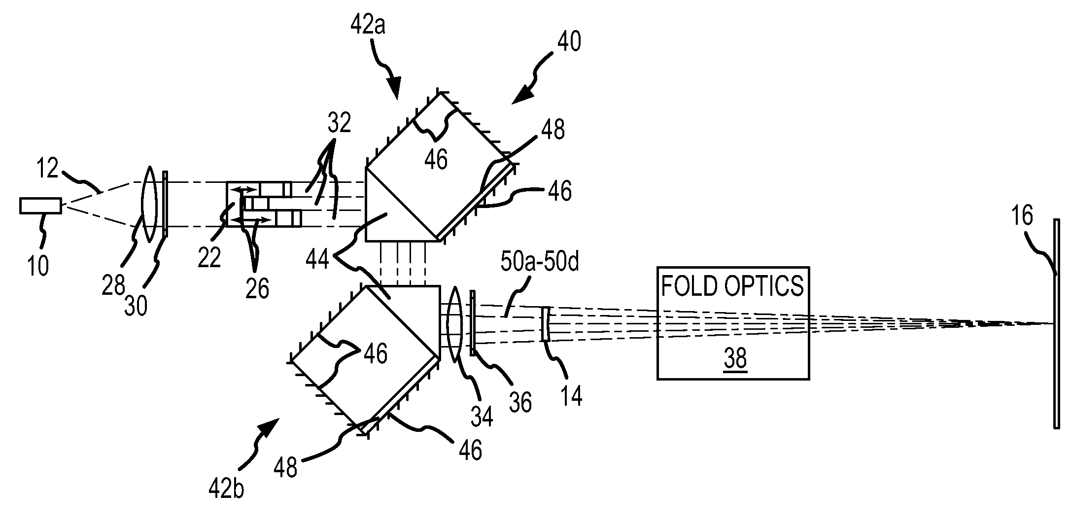
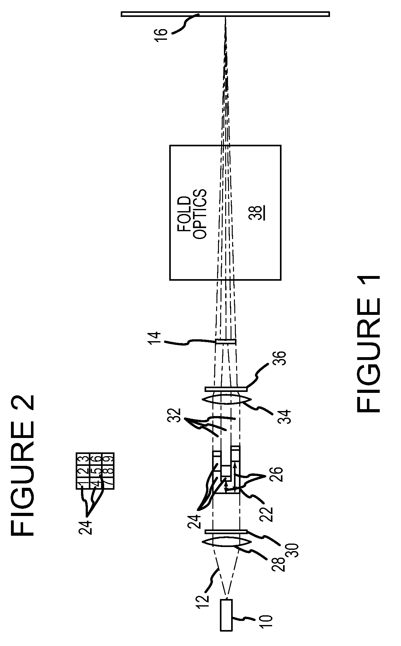
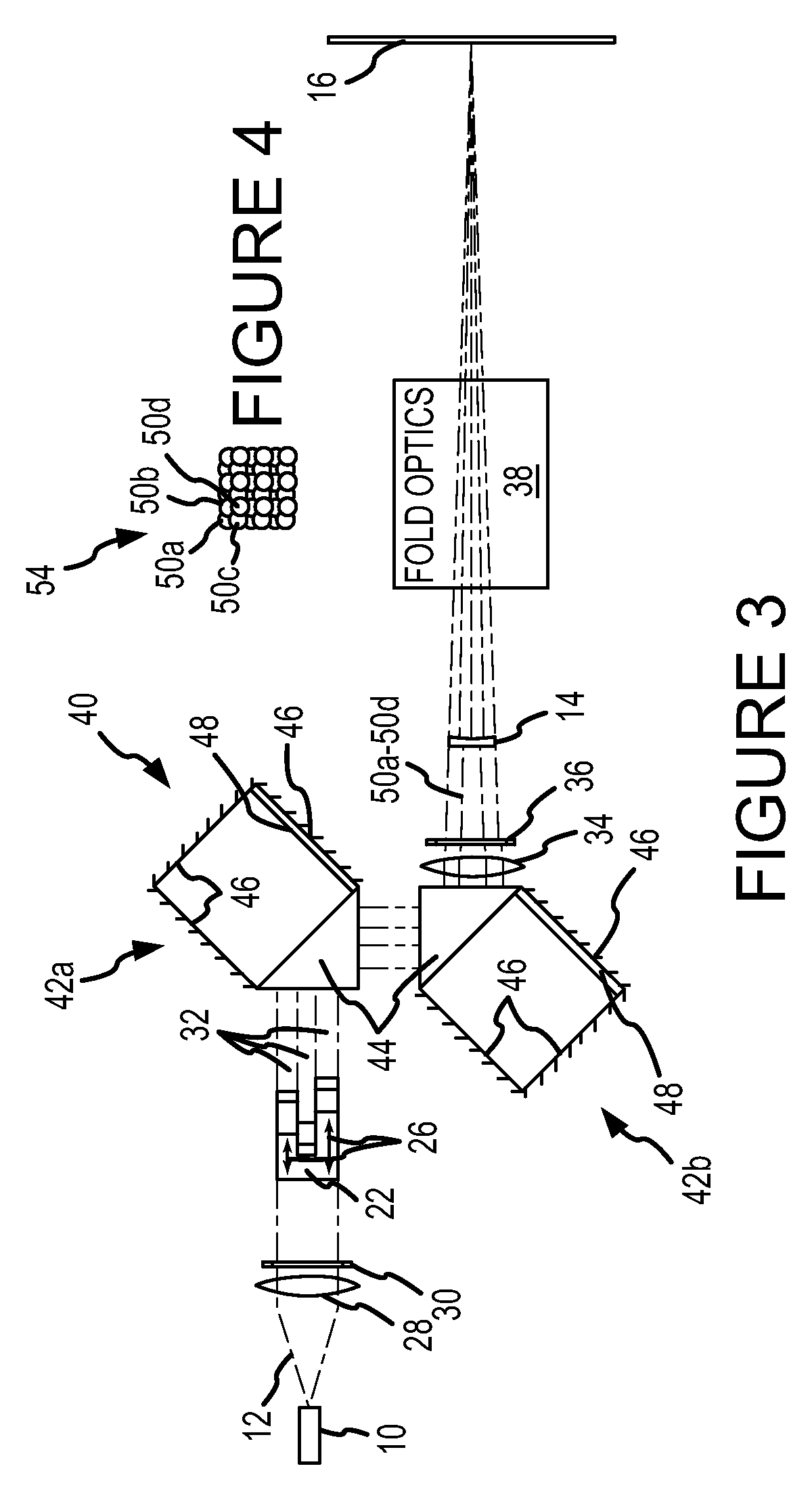
[0039]Referring to FIGS. 1 and 2, in some embodiments, speckle reduction is achieved by increasing the angular diversity of light incident on the screen 16. For example, in the embodiment of FIGS. 1 and 2, a laser 10 produces a beam 12 that is directed through a delay plate 22 having discrete regions 24. The laser 10 may have a Gaussian, top-hat, or other intensity and / or wavelength distribution. The discrete regions 24 may have different optical path lengths. Different optical path lengths may be achieved by varying the physical lengths 26 of the discrete regions 24 or by constructing the discrete regions of materials having different indices of refraction. In some embodiments, both the lengths 26 and the indices of refraction differ. The discrete regions 24 may each be square shaped, as illustrated in FIG. 2, or may be hexagonally shaped in order to form a more compact delay plate 22. Each of the discrete regions 24 may have an optical path length differing from the optical path l...


PUM


Abstract

A laser projection system is disclosed having reduced apparent speckle. The system includes a laser emitting a first beam on an optical element. The optical element emits a second beam incident on a scanner that scans the beam onto a projection screen. The optical element may be an exit pupil expander, delay plate, or have a locally electrically modulated index of refraction. In other embodiments, the laser has a tunable wavelength distribution that is changed for each frame displayed by the projection system to reduce apparent speckle. In still other embodiments, the angular content of a beam incident on a scanner is modulated to produce a time varying speckle pattern.

Description

TECHNICAL FIELD[0001]This invention relates to scanning imaging systems and more particularly to laser scanning imaging systems.BACKGROUND OF THE INVENTION[0002]In some scanned laser projection systems, a laser beam is directed at an actuated scanner that directs the beam across a projection screen. As the beam is scanned, the intensity of the laser is modulated to create light and dark areas on the projection screen to form an image. A typical projection screen will have an irregular surface that scatters the beam. As a result, portions of the beam reflected from different irregularities may be phase shifted relative to one another. Due to the coherence of the beam, if the phase shift is less than the coherence length, portions of the reflected beam will constructively and destructively interfere to form a pattern of dark and light regions often referred to as speckle. The presence of speckle often perceptibly degrades the quality of the image produced using the laser projection sy...

Claims


Application Information

Patent Timeline
IPC IPC(8): G03B21/26G03B21/28
CPCG03B21/26G03B21/28
Inventor POWELL, KARLTON D.BROWN, MARGARET K.XUE, BINMONTAGUE, THOMAS W.
Owner MICROVISION
Why Eureka
Try Eureka