Method for the wavelength calibration of a spectrometer

a spectrometer and wavelength calibration technology, applied in the direction of instruments, spectrometry/spectrophotometry/monochromators, optical radiation measurement, etc., can solve the problems of inability to produce calibrators for similar instruments produced by one manufacturer, and inability to achieve the spectral response of the instrument. , to achieve the effect of high calibration accuracy, cost-effectiveness and complicated calculation steps

Inactive Publication Date: 2008-12-04
ROCHE DIAGNOSTICS OPERATIONS INC
View PDF5 Cites 53 Cited by
  • Summary
  • Abstract
  • Description
  • Claims
  • Application Information

AI Technical Summary

Benefits of technology

The present invention provides methods for wavelength calibration that can use low-cost spectrometers with a broader bandwidth and ensure high calibration accuracy, even in analyzers for medical diagnostics. The methods also allow for the use of alternative and cost-effective light sources and avoid complicated calculation steps, making the calibration process simpler and more efficient. Additionally, the methods do not require the use of external reference media for the calibration process.

Problems solved by technology

The technical problem addressed in this patent text is the difficulty of accurately calibrating the wavelength of a spectrometer using conventional peak search methods. These methods require high resolution spectrometers with narrow bandwidth and are influenced by the optical properties of the spectrometer. The patent text proposes a new method for calibrating the wavelength of a secondary spectrometer using a reference sample with a known wavelength and intensity values. The method takes into account the measured wavelength of the reference sample and the surrounding peaks in the sample's spectrum. The new method allows for wavelength calibration of low-cost spectrometers with lower accuracy and can be used in medical diagnostic applications. The method also introduces a new method for calibrating the wavelength of a secondary spectrometer using a reference sample with a known wavel length and intensity values. The new method is more accurate for low-resolved peaks and can use alternative light sources for wavelength calibration.

Method used


Image

  • Method for the wavelength calibration of a spectrometer
  • Method for the wavelength calibration of a spectrometer
  • Method for the wavelength calibration of a spectrometer

Examples


example 1

[0110]Example 1 describes a specific embodiment of a method according to the invention analogous to the third typical embodiment.

[0111]A wavelength calibration is carried out according to the inventive method on a grating spectrometer designated CP20 from the Jobin Yvon Company (Longjumeau Cedex, France). This spectrometer has a linear line sensor with 256 pixels, can resolve a wavelength range of 638 to 1038 nm, and has a spectral bandwidth of about 8 nm.

[0112]A first CP20 spectrometer is defined as the primary spectrometer, and another CP20 spectrometer of the same type is defined as the secondary spectrometer. A first wavelength assignment which was carried out in the factory by the manufacturer using a conventional peak search method was available for both spectrometers and enclosed with the spectrometers. In the specific case the wavelength assignment is a polynomial of the 3rd degree (λ−a0+a1 x+a2 x2+a3 x3) and the four coefficients a0, a1, a2 and a3 for the wavelength assignm...

example 2

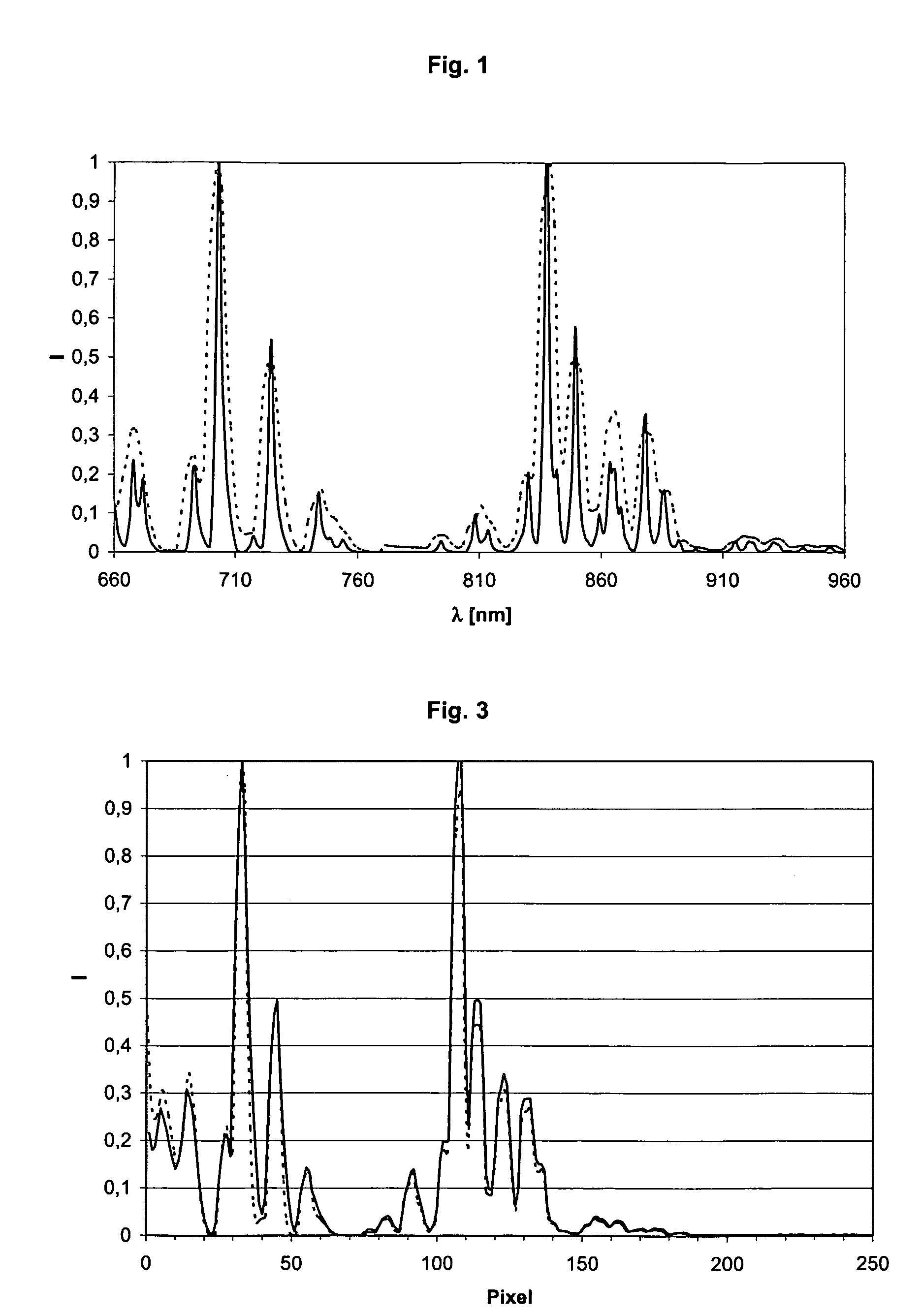
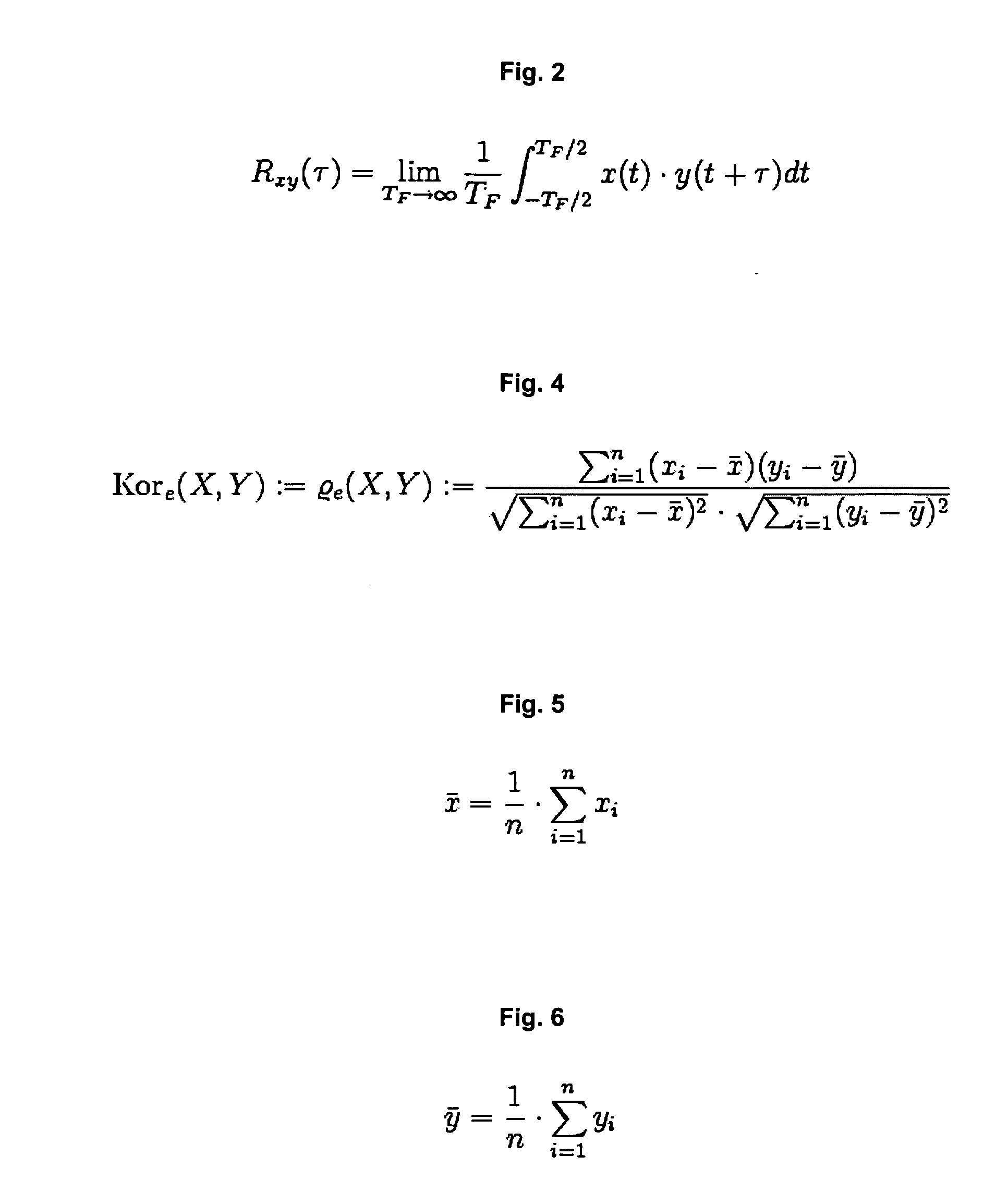
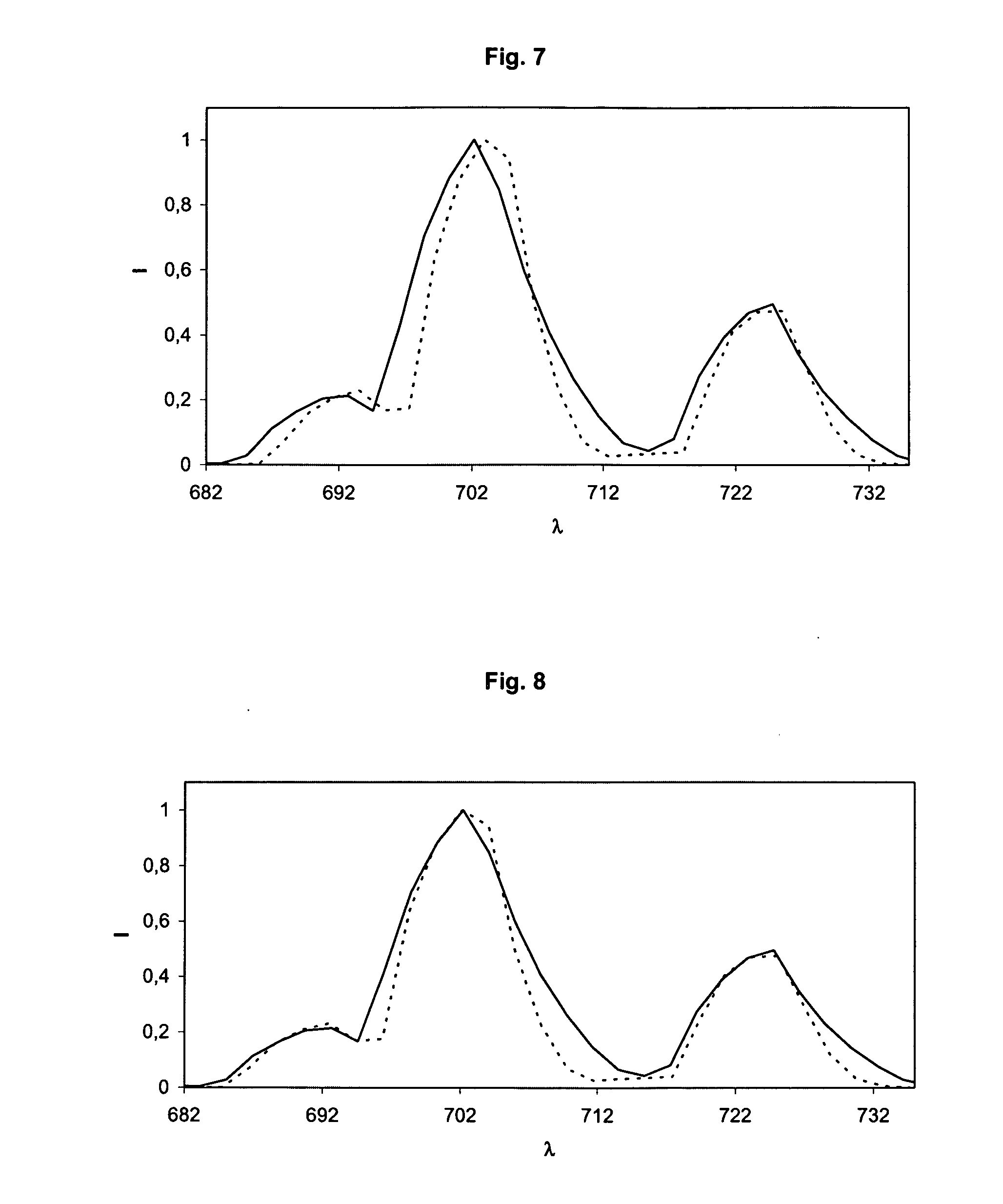
[0122]In order to demonstrate and quantify the advantages of the method according to the invention compared to the previously used peak search methods, the wavelength calibration of spectrometers is simulated on a spectrum of a neon lamp in a wavelength range of 655 to 1035 nm at various calculated broadenings of the band-width. A neon spectrum is measured with a grating spectrometer of the type CP140 from the Jobin Yvon Company (Longjumeau Cedex, France) with a spectral band-width of 2 nm as a basis for the simulation. Simulated spectra with a respective bandwidth of 6, 7.5, 9 and 12 nm are calculated from this data set by a sliding multiplication using a Gauss curve adapted to each case. Wavelength calibrations are carried out on these various spectra a) with the peak search method and b) with the method according to the invention and the respective maximum errors are calculated over the entire wavelength range. These errors are listed in table 1. The errors are calculated in this...


PUM


Abstract

The invention concerns methods for the wavelength calibration of spectrometers and in particular secondary spectrometers which achieve considerably better calibration accuracies than the conventional peak search methods especially for spectrometers with a relatively large bandwidth. The methods according to the invention are based on the principle of a stepwise relative shift of corresponding measured-value blocks of a model and calibration spectrum where a correlation value is calculated for each shift step. A shift value is determined for each measured-value block at which the correlation value reaches an optimum. A value pair consisting of a position marker of the measured-value block and the associated shift value is determined for each measured-value block. These value pairs represent the design points for fitting to a suitable assignment function. The coefficients obtained in this manner can be used directly as coefficients of a wavelength assignment or be combined with the coefficients of an existing first wavelength assignment in that they for example replace these coefficients or are offset against the coefficients of an existing first wavelength assignment.

Description


Claims


Application Information

Patent Timeline
Owner ROCHE DIAGNOSTICS OPERATIONS INC
Why Eureka
Try Eureka