Testing Apparatus, System, and Method for Testing at Least One Device with a Connection Interface

a technology of connection interface and test apparatus, applied in the direction of error detection/correction, instruments, computing, etc., can solve the problems of system shutdown and stopping the testing of other tested devices, time-consuming use of two test machines, and inability to achieve the testing process. cost

Inactive Publication Date: 2008-12-04
SILICON MOTION INC (TW)
View PDF22 Cites 45 Cited by
  • Summary
  • Abstract
  • Description
  • Claims
  • Application Information

AI Technical Summary

Benefits of technology

[0014]With the aforementioned arrangement, the present invention is able to provide a testing apparatus and a system f

Problems solved by technology

Using two test machines is time consuming.
Since all tested devices need to be tested at the same time in the traditional test methodology, omitting open/short tests (also known as the over current fail test) will cause the system to shut down and stop testing other tested devices.
Thus, the

Method used


Image

  • Testing Apparatus, System, and Method for Testing at Least One Device with a Connection Interface
  • Testing Apparatus, System, and Method for Testing at Least One Device with a Connection Interface
  • Testing Apparatus, System, and Method for Testing at Least One Device with a Connection Interface

Examples


Embodiment Construction

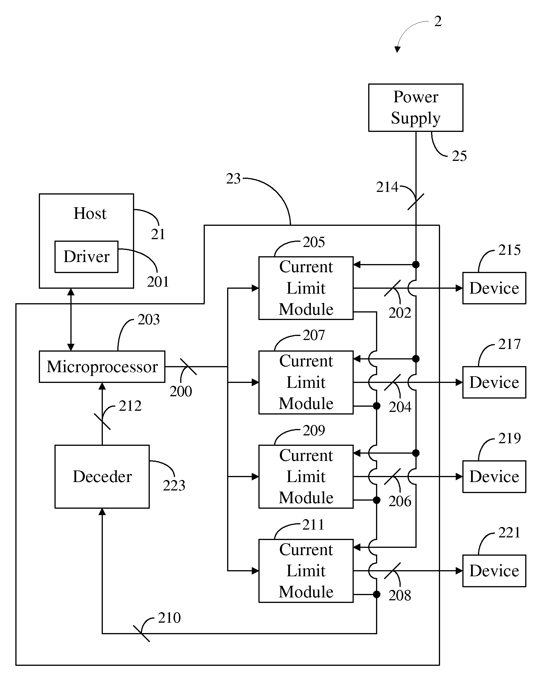
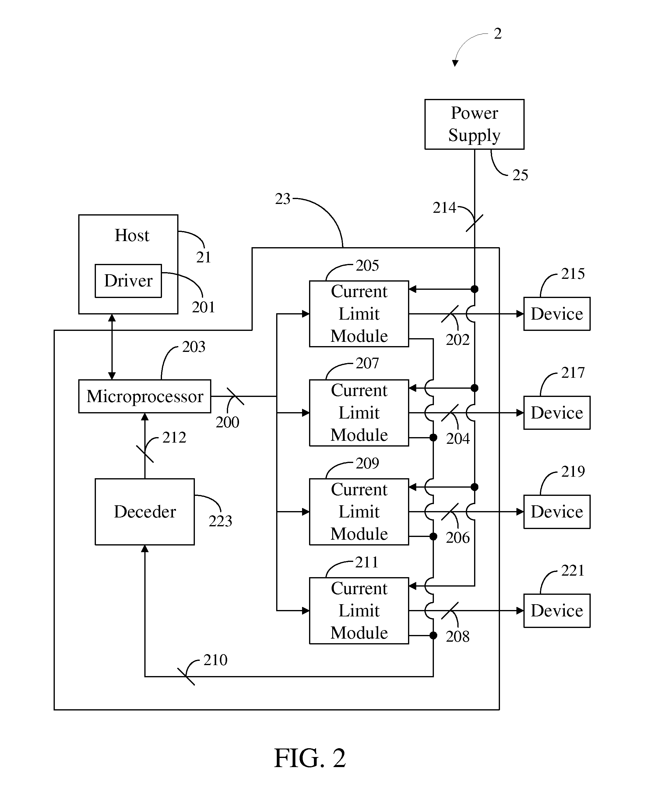
[0019]A first embodiment of the present invention is a system 2 for testing a plurality of devices with a connection interface as illustrated in FIG. 2. The connection interface is the USB connection interface or the IEEE 1394 connection interface, etc. For simplification, four devices (devices 215, 217, 219, and 221) are illustrated. The system 2 comprises a host 21, a testing apparatus 23, and a power supply 25. The testing apparatus 23 comprises a microprocessor 203, a plurality of current limit modules 205, 207, 209, 211, and a decoder 223.

[0020]The host 201 respectively sends an enable signal 200 to the current limit module 205, 207, 209, and 211 (hereinafter referred as 205˜211) via the microprocessor 203 to enable devices 215, 217, 219, and 221 (hereinafter referred as 215˜221).

[0021]Each of the devices 215˜221 has a connection interface. The devices 215˜221 are respectively connected to the corresponding current limit module 205˜211 through the corresponding connection inter...


PUM


Abstract

A system, a testing apparatus, and a method for testing at least one device with a connection interface are provided. The system comprises a host, a testing apparatus, and a power supply. The testing apparatus further comprises a microprocessor and at least one current limit module. The host sending a test signal. The power supply provides a voltage to the testing apparatus. The at least one current limit module of the testing apparatus, which is electrically connected to the microprocessor, the at least one device, and the power supply, provides the voltage to the at least one device. When the current passing through the at least one device is greater than the predetermined value, the at least one current limit module of the testing apparatus stops providing the voltage to the at least one device and sends an over current signal to the host via the microprocessor.

Description

[0001]This application claims the benefit of Provisional Application Ser. No. 60 / 941,720 filed on Jun. 4, 2007.CROSS-REFERENCES TO RELATED APPLICATIONS[0002]Not ApplicableBACKGROUND OF THE INVENTION[0003]1. Field of the Invention[0004]The present invention relates to a testing apparatus, a system, and a method for testing at least one device with a connection interface; more specifically, the present invention relates to a testing apparatus, a system, and a method for testing at least one device with a connection interface by sensing an over current.[0005]2. Descriptions of the Related Art[0006]As capacity and utility of devices using the universal serial bus (USB) connection interfaces or the IEEE 1394 connection interfaces are improved, the prices thereof are becoming more reasonable. Devices with the foregoing interfaces are popular, such as flash memory card readers, USB flash drives (UFDs), and portable hard drives. These devices are adaptable to computer USB ports.[0007]After ...

Claims


Application Information

Patent Timeline
IPC IPC(8): G06F11/00
CPCG06F11/24
Inventor CHUNG, MING-KUNCHIANG, CHANG-HAOHUANG, KUO-TUNG
Owner SILICON MOTION INC (TW)
Why Eureka
Try Eureka