Square Tube Forming Roll, Square Tube Forming Method, and Forming Device

US20080302160A1Inactive Publication Date: 2008-12-11NAKATA MFG

Image

  • Square Tube Forming Roll, Square Tube Forming Method, and Forming Device
  • Square Tube Forming Roll, Square Tube Forming Method, and Forming Device
  • Square Tube Forming Roll, Square Tube Forming Method, and Forming Device

Examples


Embodiment Construction

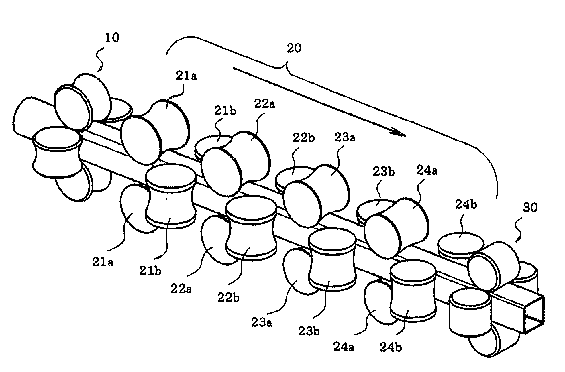
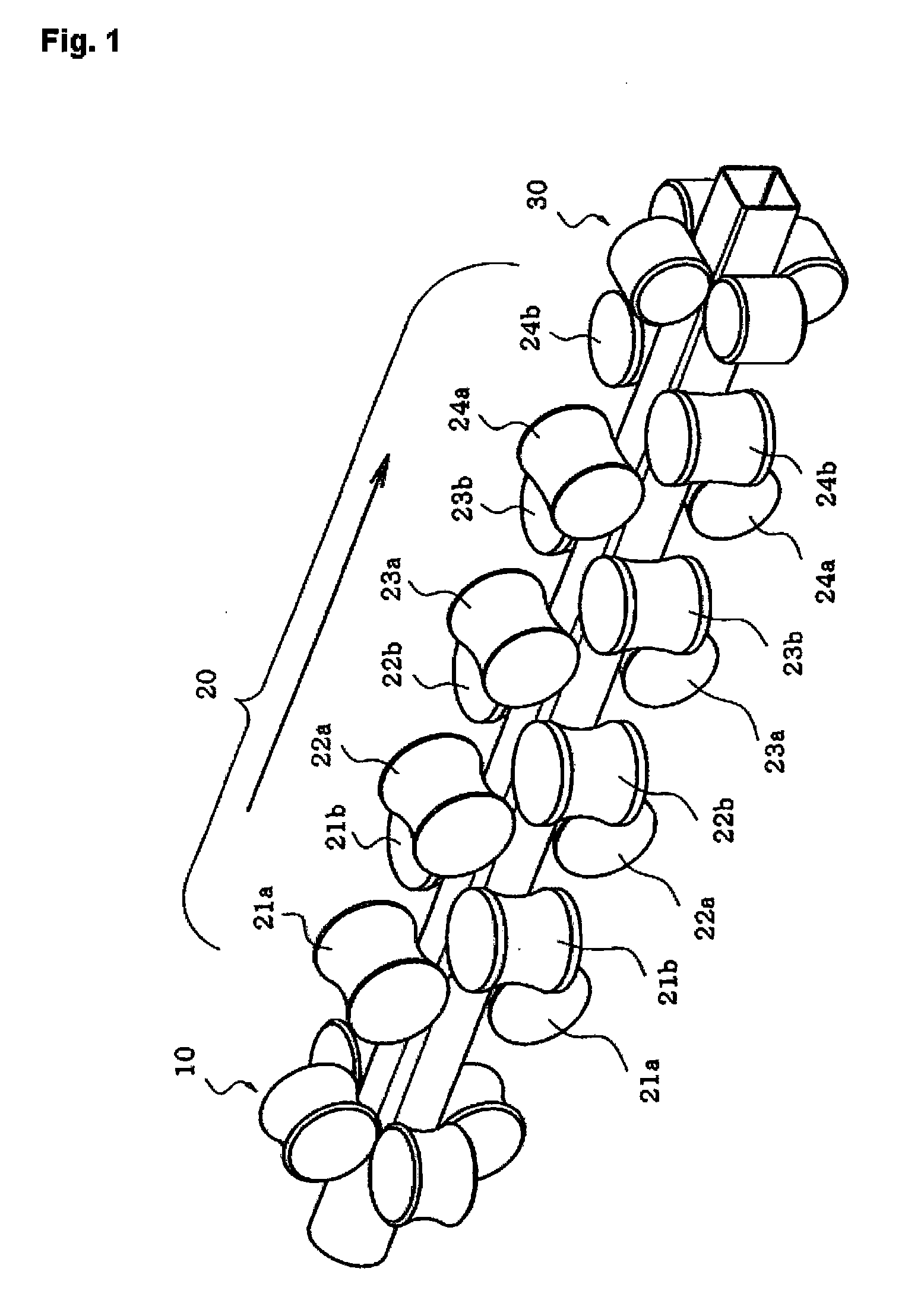
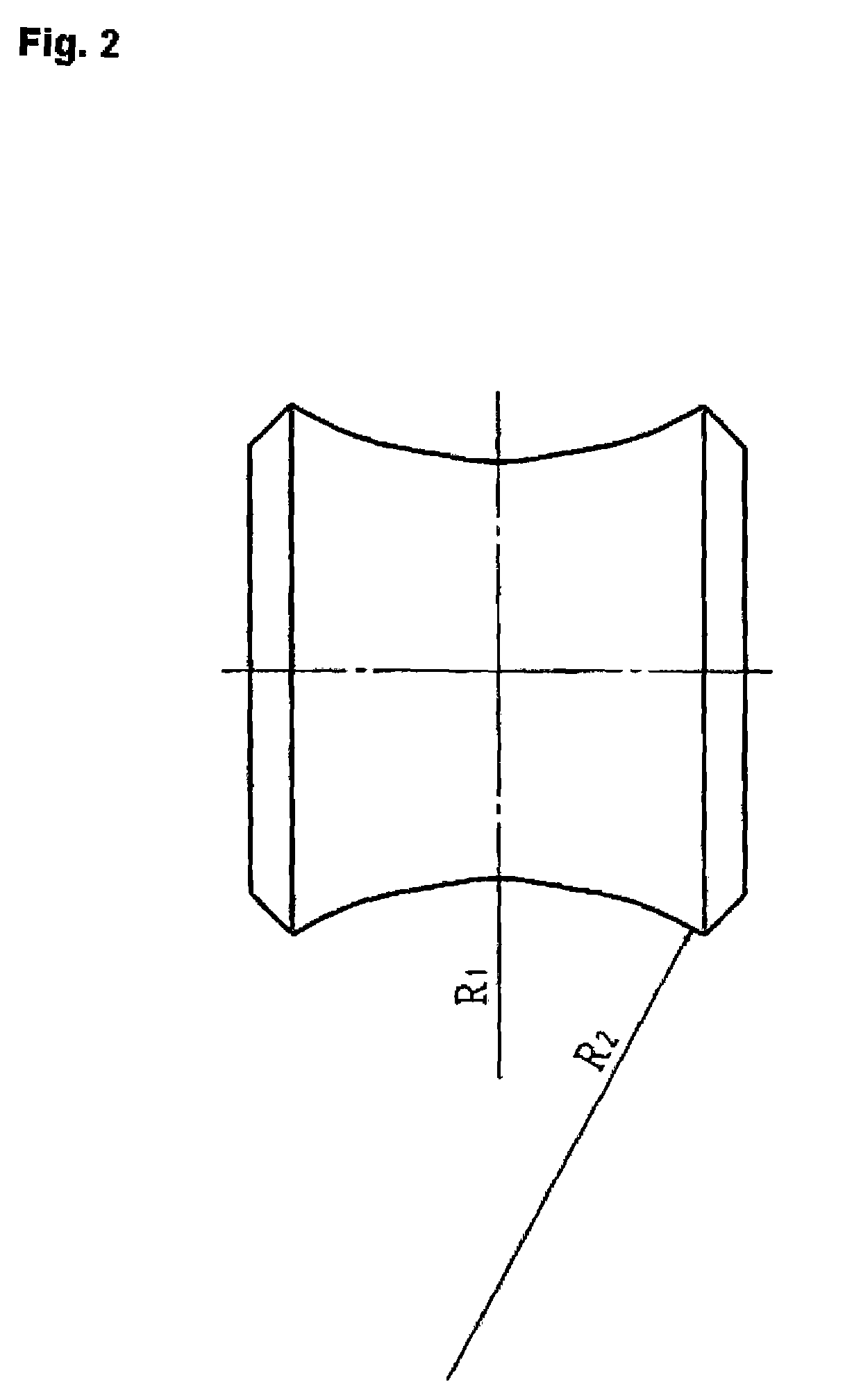
[0043]The inventors noticed the adoption of a shape in a single arc having fixed curvature (R) in relation to the rotational axis direction as shown in FIG. 9 in the portion forming the circumferential surface shape of the forming roll, which is called a roll caliber, for the square tube forming device of the former method, including of any of the previously described former methods.

[0044]Specifically, when using forming rolls as with the former methods, the straightening of the raw tube portions to become each portion of the side portions of the square tube at each stage of the forming process is performed successively at an identical pace, but at the final stage of the process at which is performed finishing of the corner portions (FIG. 4Aβ€œa” and FIG. 4Bβ€œA”) and side portions, in the side portions (FIG. 4Aβ€œb” and FIG. 4Bβ€œB”) adjacent to the corner portions, because there is not sufficient obtaining of bending moment required for straightening in comparison to the center portions o...


PUM


Abstract

Roll forming a round tube to a square tube without applying excessive load to the raw tube scheduled portions to become corner portions and shoulder portions. This invention structures the curvature of the rotation axis direction of the forming roll surface in a way that in relation to other raw tube locations (straightening precedes for the raw tube locations adjacent to the corner portion scheduled locations of the square tube. It disposes stands of four-direction roll structure at the forming roll stand furthest upstream and furthest downstream sides and disposes stands of upper-lower and left-right two-direction roll structure between the upstream and downstream roll stands, and by adopting forming roll with a structure having a curvature for constricting the raw tube locations to become the shoulder portions adjacent to the corner portions of the square tube at a smaller curvature than that constricting the raw tube portions to become the side portion centers of the square tube cross section.

Description

CROSS REFERENCE TO PRIOR APPLICATION[0001]This is a U.S. national phase application under 35 U.S.C. Β§ 371 of International Patent Application No. PCT / JP2004 / 019825 filed Dec. 27, 2004, and claims the benefit of Japanese Application No. 2004-341516 filed Nov. 26, 2004 all of which are incorporated by reference herein. The International Application was published in Japanese on Jun. 1, 2006 as International Publication No. WO 2006 / 057074 under PCT Article 21(2).TECHNICAL FIELD[0002]In relation to forming rolls and pursuant forming methods and devices for re-forming of round tubes to square tubes, this invention is related to square tube forming rolls achieving multi-use implementation for forming rolls and to roll forming methods and forming devices for square tubes.BACKGROUND OF THE INVENTION[0003]Many structures are proposed that have forming methods and devices utilizing forming rolls to re-form round tubes of circular cross section to square tubes of square or rectangular cross sec...

Claims


Application Information

Patent Timeline
11 Dec 2008
Publication
US20080302160A1
IPC
B21C37/15; B21D5/12
CPC
B21B17/14; B21C37/155; B21D5/12; B21D15/02; B21D3/02
Inventors
WANG, FEIZHOU; NAKANO, TOMOYASU