
Automatic by-pass safety cooling system for fire pump engines

Inactive Publication Date: 2008-12-11
TOJALI
View PDF34 Cites 14 Cited by
  • Summary
  • Abstract
  • Description
  • Claims
  • Application Information

AI Technical Summary

Benefits of technology

[0008]The foregoing and other objects of the present invention are achieved by my invention which is described in more detail below.
[0009]To achieve the above mentioned objects it has been surprisingly discovered that by providing an independent and automatic by-pass safety cooling system that is responsive solely and directly to the engine jacket coolant temperature that continued cooling of the engine will occur without reliance upon any other control systems, panels, or personnel. In a stationary installation, the engine, once started, will continue to run; and; since the engine jacket coolant pump is built into the engine, as long as the engine is running, the jacket coolant will be circulating. However, the problem is to insure continued cooling water to the heat exchanger that cools the engine jacket coolant. This is solved by the redundant back up system of the present invention.
[0010]Accordingly, in one aspect the present invention is a novel automatic by-pass safety cooling system which includes valve means connecting an independent water supply to said heat exchanger. The independent water supply is the supply to the fire pump which may come from a municipal system, tank, or a reservoir. The system further includes a temperature sensing means or sensor located in the engine jacket for detecting the temperature of the engine jacket coolant and means responsive to said temperature sensing means to automatically open said valve through a recording hour meter means at a pre-set temperature level thereby delivering water from the independent supply to the heat exchanger, said valve means being solely and directly actuated by the sensing means. Preferably, the system includes a water pressure control means and a preferred first pre-set temperature level which is preferably about 185° F. The system also preferably includes a recording meter that will record the jacket operating temperature history. A second sensor independent from the first is preferably included

Problems solved by technology

However, the problem is to insure continued cooling water to the heat exchanger that cools the engine jacket coolant.

Method used


Image

  • Automatic by-pass safety cooling system for fire pump engines
  • Automatic by-pass safety cooling system for fire pump engines
  • Automatic by-pass safety cooling system for fire pump engines

Examples


Embodiment Construction

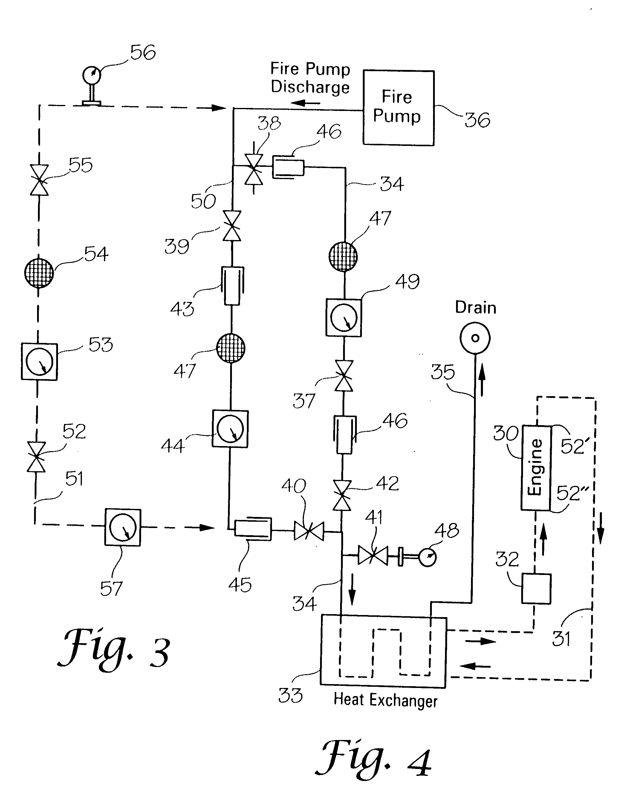
[0019]Looking first at FIG. 4, a standard cooling loop layout is schematically shown, FIG. 3 being the left hand side of the sheet displaying FIGS. 3 and 4. Such a layout may be found in the NFPA Engine Driven Fire Pump Manual. In FIG. 4, engine 30 is represented with a cooling pump 32 which is driven directly from the engine and is built into the engine. The cooling loop contains the engine coolant which generally will be an ethylene glycol / water mixture and the coolant circulates through the water cooled tube and shell heat exchanger 33 where its heat is discharged. As the coolant is circulated in coolant tubes inside the heat exchanger water from the primary water supply line 34 which is water shunted or tapped off the discharge from the fire pump 36 as it is being driven by the engine. This water circulates around the coolant tubes and is dumped down the drain 35 rather than being recirculated.

[0020]The fire pump 36 may supply water directly to fire hoses to put out fires and al...


PUM


Abstract

In an internal combustion engine system where the heat in the engine jacket coolant is discharged in a water cooled heat exchanger, an independent and automatic by-pass safety cooling system responsive solely and directly to engine jacket coolant temperatures to ensure that cooling of the engine will continue without reliance upon any other control system or personnel.

Description

CROSS REFERENCE TO RELATED APPLICATION[0001]This application is a continuation-in-part of U.S. application Ser. No. 11 / 810,892, filed Jun. 07, 2007 having the same title.FIELD OF THE INVENTION[0002]This invention relates to a safety by-pass system for providing cooling water to the heat exchanger which removes heat from the coolant of a diesel engine that drives a fire pump, the by-pass system being independent from the presently used fire pump controller and cooling loop controls. More particularly, the invention relates to a system that protects stationary fire pump installations at industrial facilities, office and commercial facilities, residential complexes, hospitals, airports, and large marinas by protecting the ability of a fire pump or sprinkler systems to continue to operate.BACKGROUND OF THE INVENTION[0003]Most large industrial plants, high rise office and residential buildings, airports, warehouse facilities, military installations, and educational institutions have spri...

Claims


Application Information

Patent Timeline
IPC IPC(8): F01P5/14F01P5/10G05D23/185
CPCF01P5/14F01P7/16F01P2025/04F01P2025/31F01P2031/00
Inventor BROWN, MYRON L.
Owner TOJALI
Learn More