Solar cell module retaining structure, frame for solar cell module, and holding member for solar cell module

a solar cell module and solar cell technology, applied in the direction of heat collector mounting/support, pv power plants, lighting and heating apparatus, etc., can solve the problems of increasing the number of members, increasing manufacturing costs, and reducing the strength of solar cell module attachment, so as to improve the design of solar cell module and reduce manufacturing and installation costs

Active Publication Date: 2008-12-11
YANEGIJUTSUKENKYUJO CO LTD
View PDF2 Cites 166 Cited by
  • Summary
  • Abstract
  • Description
  • Claims
  • Application Information

AI Technical Summary

Benefits of technology

[0014]Also, after fixing one solar cell module to the supporting member via the frames by the holding member, the frame of the other solar cell module can be fixed by the holding member, so that plural solar cell modules may be fixed from one direction in order, which helps to establish the installation standard and reduce the cost of manufacturing. Also, when the holding member is fixed to the supporting member, since a portion of the holding member to be fixed to the supporting member is being fixed to the supporting member at the lower side of the other solar cell module, the frames are contacting each other. Furthermore, the solar cell modules are arranged to make an almost flush surface, thereby eliminating a clearance between the solar cell modules, which improves the design, and eliminating an unnecessary member such as a cover.
[0046]As stated above, according to this invention, by reducing the number of members relating to the solar cell module retaining structure and standardizing the installation process, this invention provides the solar cell module retaining structure, solar cell module frame, and the holding member which reduce the cost of manufacturing and installation.

Problems solved by technology

However, in the conventional solar cell module retaining structure as described in the Patent Document 1, since the sway braces 82 for the installation of the frame 81 on the sheathing slope 41 are integrally arranged with a predetermined pitch, predetermined positions of the rafters supporting the sheathing slope 41 often do not match positions of the sway braces 82 of the solar cell modules, and the sway braces 82 are not fixed on the rafters properly, thereby creating a chance of reducing the strength of solar cell module attachment.
Also, shapes of the downward pitch side frame 80 and the upward pitch side frame 81 of the solar cell module are different, which increases the number of members and further requires more complex processing of forming sway braces 82 increasing the cost of manufacturing.

Method used


Image

  • Solar cell module retaining structure, frame for solar cell module, and holding member for solar cell module
  • Solar cell module retaining structure, frame for solar cell module, and holding member for solar cell module
  • Solar cell module retaining structure, frame for solar cell module, and holding member for solar cell module

Examples


Embodiment Construction

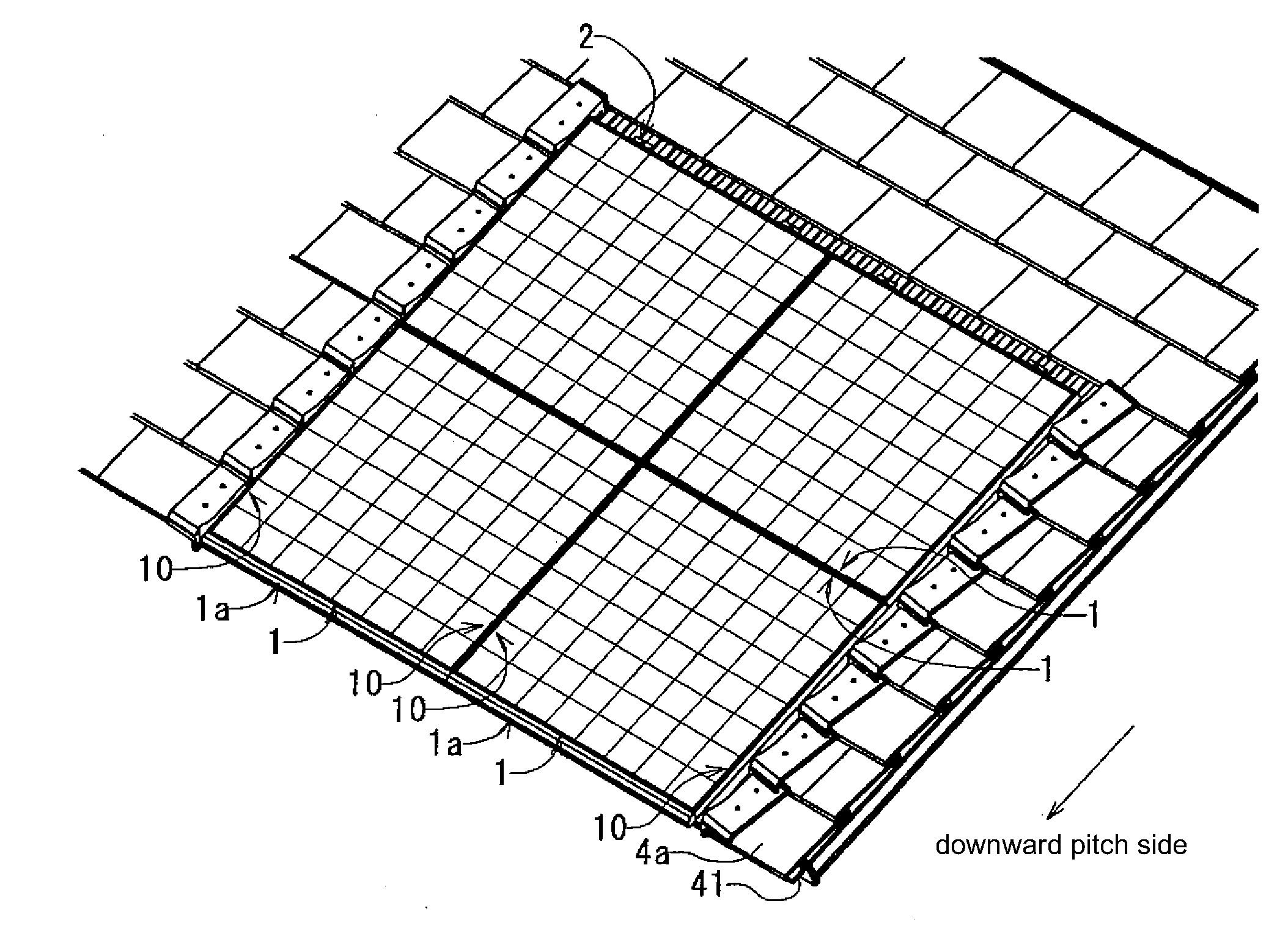
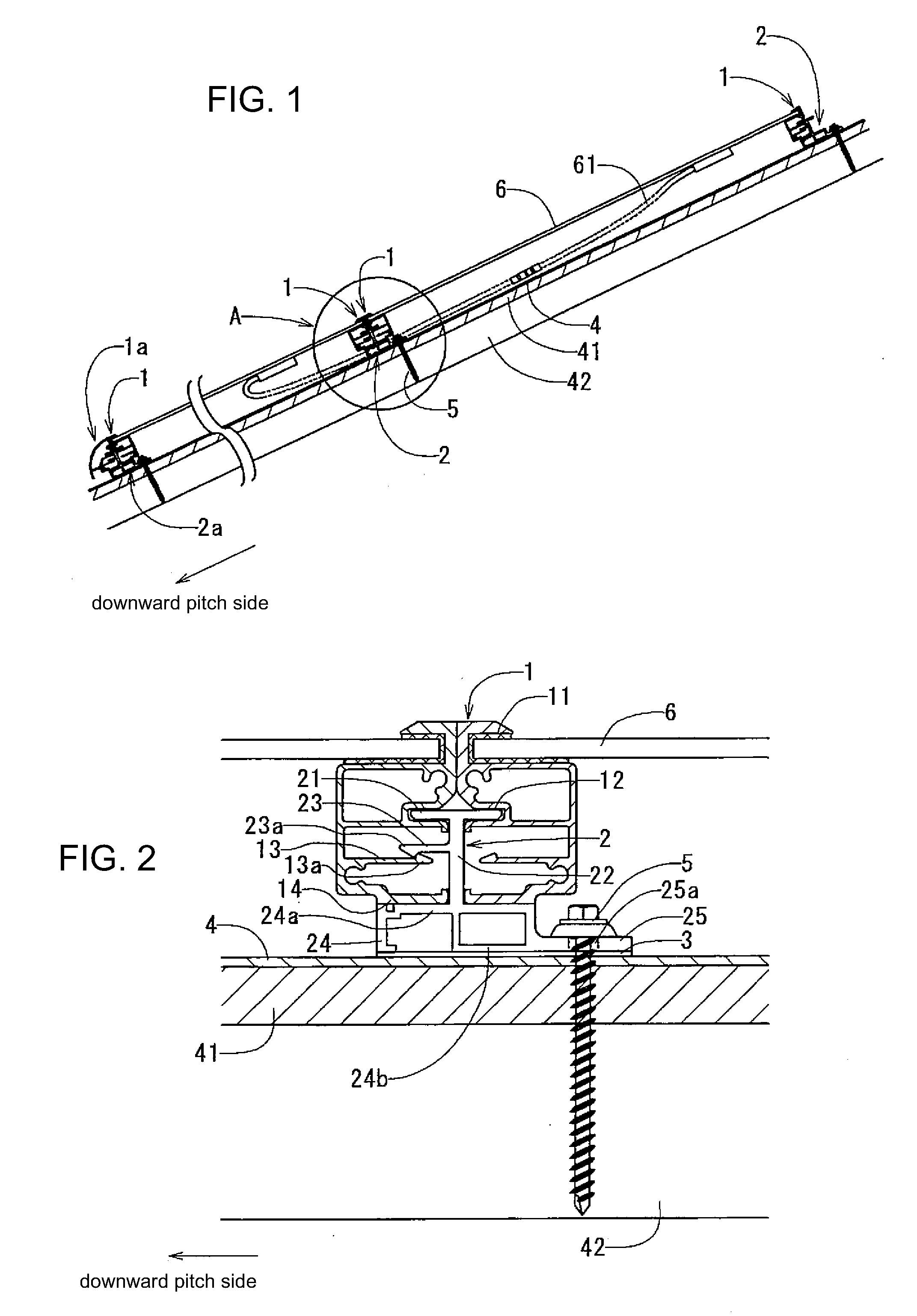
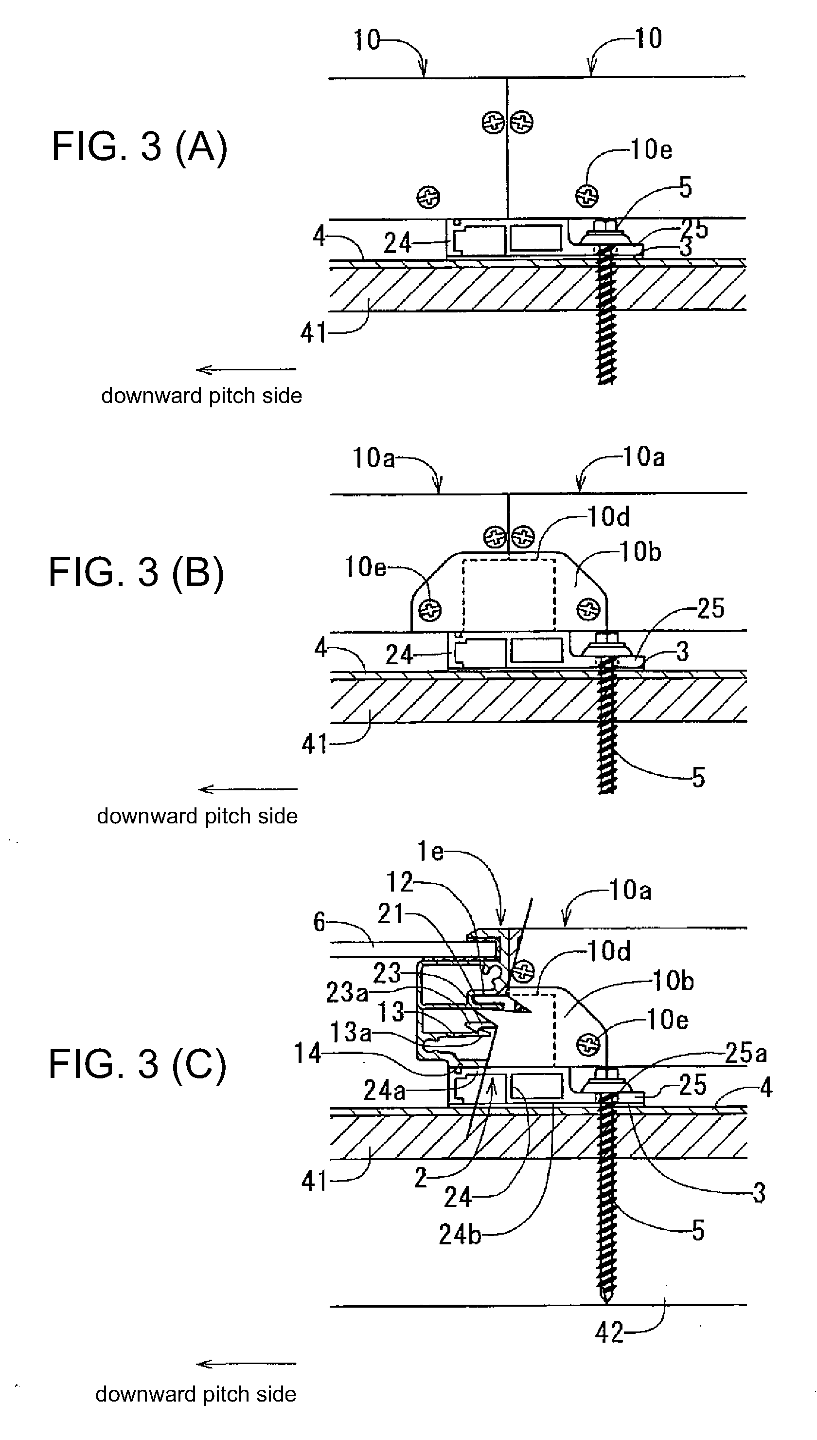
[0058]In the following sections, preferred embodiments of this invention for the solar cell module retaining structure, frames for the solar cell modules, and holding members for the solar cell modules will be explained with reference to FIGS. 1-5. FIG. 1 is a cross section view of one embodiment of this invention showing the frames for the solar cell modules and the solar cell module retaining structure using the holding members. FIG. 2 is an enlarged cross section view of the details of A in FIG. 1. FIG. 3(A) is a side surface view of FIG. 2; FIG. 3(B) is a side surface view of the side surface frames and side surface caps different from FIG. 3(A); and FIG. 3(C) is a side surface view of one portion FIG. 3(B) in cross section. FIG. 4 is an explanation view of the installation process summary for the solar cell module in FIGS. 1 and 2. FIG. 5(A) is a perspective view of the condition where the solar cell module is installed on the roof material using the solar cell module retaining...


PUM


Abstract

To provide the solar cell module retaining structure, the frame for the solar cell module, and the holding member for the solar cell module, which reduces the number of members relating to the solar cell module retaining structure, standardizes the installation process thereof, and reduces the cost of manufacturing and installing. The solar cell module retaining structure is to fix the solar cell module which comprises the solar cell panel body with the modular glass (6) and the frame (1) to be fixed to the solar panel body to the supporting member (42) via the holding member (2), wherein the frame (1) and the holding member (2) are for the retaining structure of the solar cell module; the holding member (2) can slide relative to the frame (1); the holding member (2) can keep two adjacent frames of two adjacent solar cell modules contacted and restrict one solar cell module from moving in the right angle direction relative to the extending direction of the frame (1); and the holding member (2) is fixed to the supporting member (42) at the lower side of the other solar cell module.

Description

FIELD OF THE INVENTION[0001]This invention relates to a retaining structure to fix a solar cell module on a roof and a frame and a holding member for the solar cell module.BACKGROUND OF THE INVENTION[0002]A solar cell module retaining structure to be installed directly on a sheathing slope without placing on a roof material is known as a conventional retaining structure for the solar cell module. For example, as shown in FIG. 6(A), a sway brace 82 is formed on an upward pitch side frame 81 of the downward pitch side solar cell module of two frames 80, 81 of two adjacent solar cell modules extending perpendicularly relative to a downward pitch direction, and the sway brace 82 is tied to a sheathing slope 41, while a upward pitch side fitting portion 84 formed on the upward pitch side frame 81 of the downward pitch side solar cell module fits with a upward fitting portion 83 formed on the downward pitch side frame 80 of the upward pitch side solar cell module (Patent Document 1).[0003...

Claims


Application Information

Patent Timeline
Patent Type & Authority Applications(United States)
IPC IPC(8): H01L31/048E04D13/18F24J2/52
CPCF24J2/5211F24J2/5245F24J2/5254F24J2/5262H02S20/23Y02B10/12Y02B10/20Y02E10/47F24J2002/4663F24S25/20F24S25/61F24S25/632F24S25/67F24S2025/6003Y02B10/10Y02E10/50E04D13/00H01L31/042
Inventor KOBAYASHI, SHUICHI
Owner YANEGIJUTSUKENKYUJO CO LTD
Why Eureka
Try Eureka