Removable Injection or Production Flow Equalization Valve

Active Publication Date: 2008-12-11
BAKER HUGHES INC
View PDF59 Cites 8 Cited by
  • Summary
  • Abstract
  • Description
  • Claims
  • Application Information

AI Technical Summary

Benefits of technology

[0005]One or more valves can be run into a string to land near associated ports in the string for injection or/and production service. When multiple valves are installed they can be initially configured to balance flow into or from a zone. The position of each valve can be altered without removal from the string preferably by

Problems solved by technology

In some well bores multiple zones may be present which present problems of metering the desired quantities of injected fluids into the individual zones from a single tubing or casing string.
Injection can require high pressures and flow rates, which means it generally involves high fluid velocities.
High fluid velocities are detrimental to equipment such as valves through which the injected material is pumped.
The problem with side pocket mandrels was that additional space was needed in the well to get the side pocke

Method used


Image

  • Removable Injection or Production Flow Equalization Valve
  • Removable Injection or Production Flow Equalization Valve
  • Removable Injection or Production Flow Equalization Valve

Examples


Example

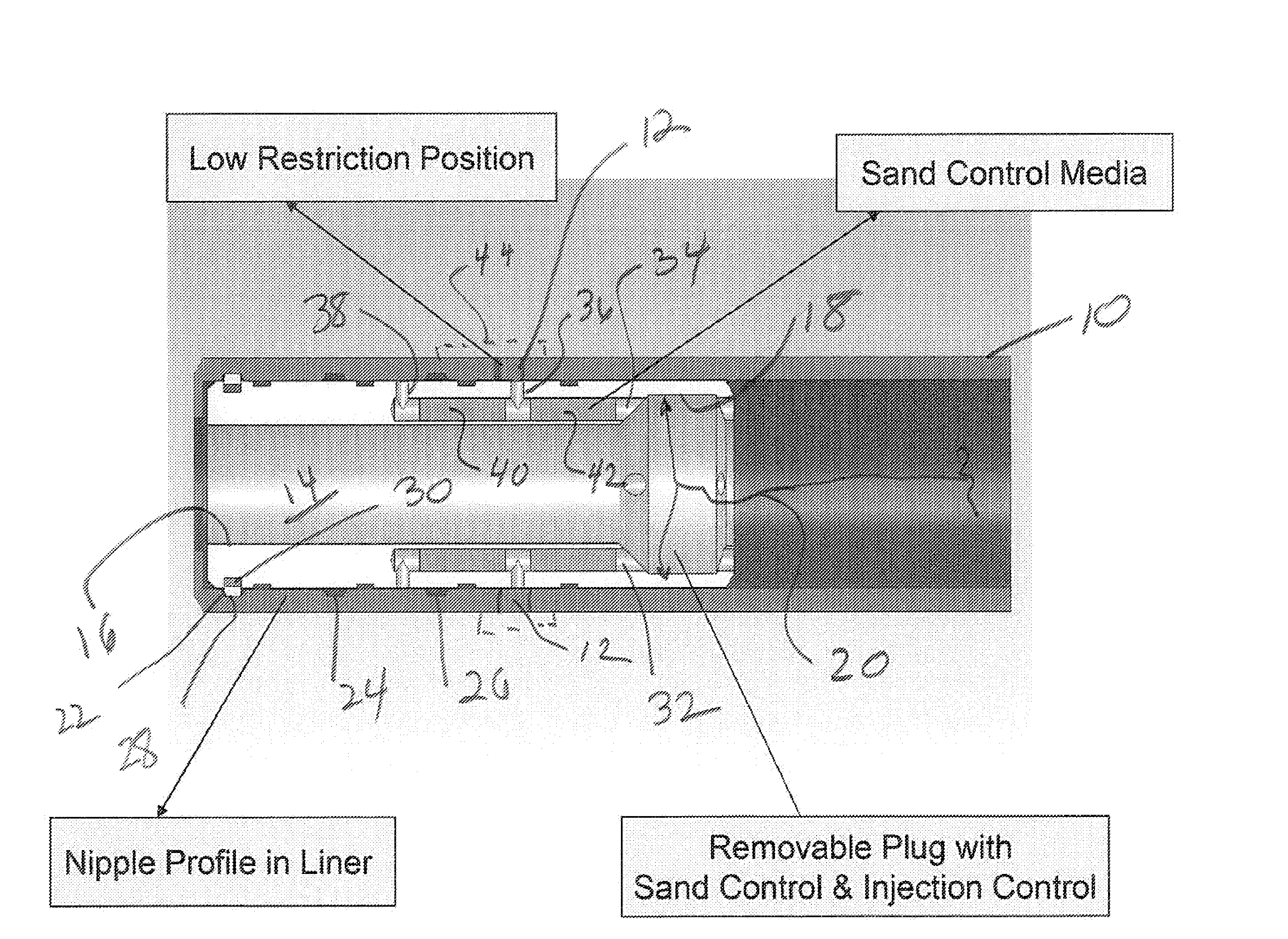
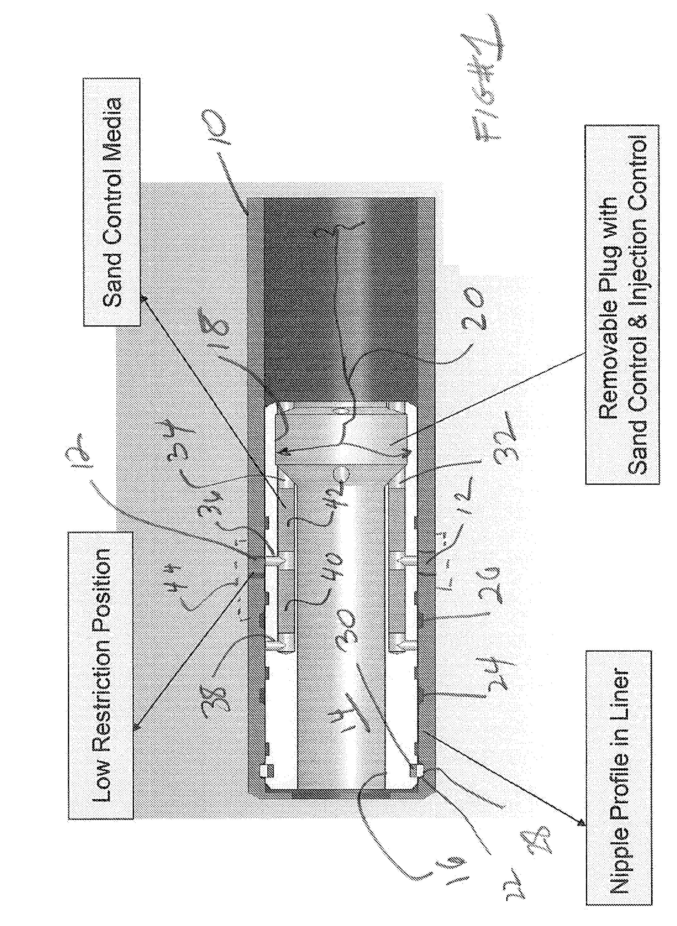
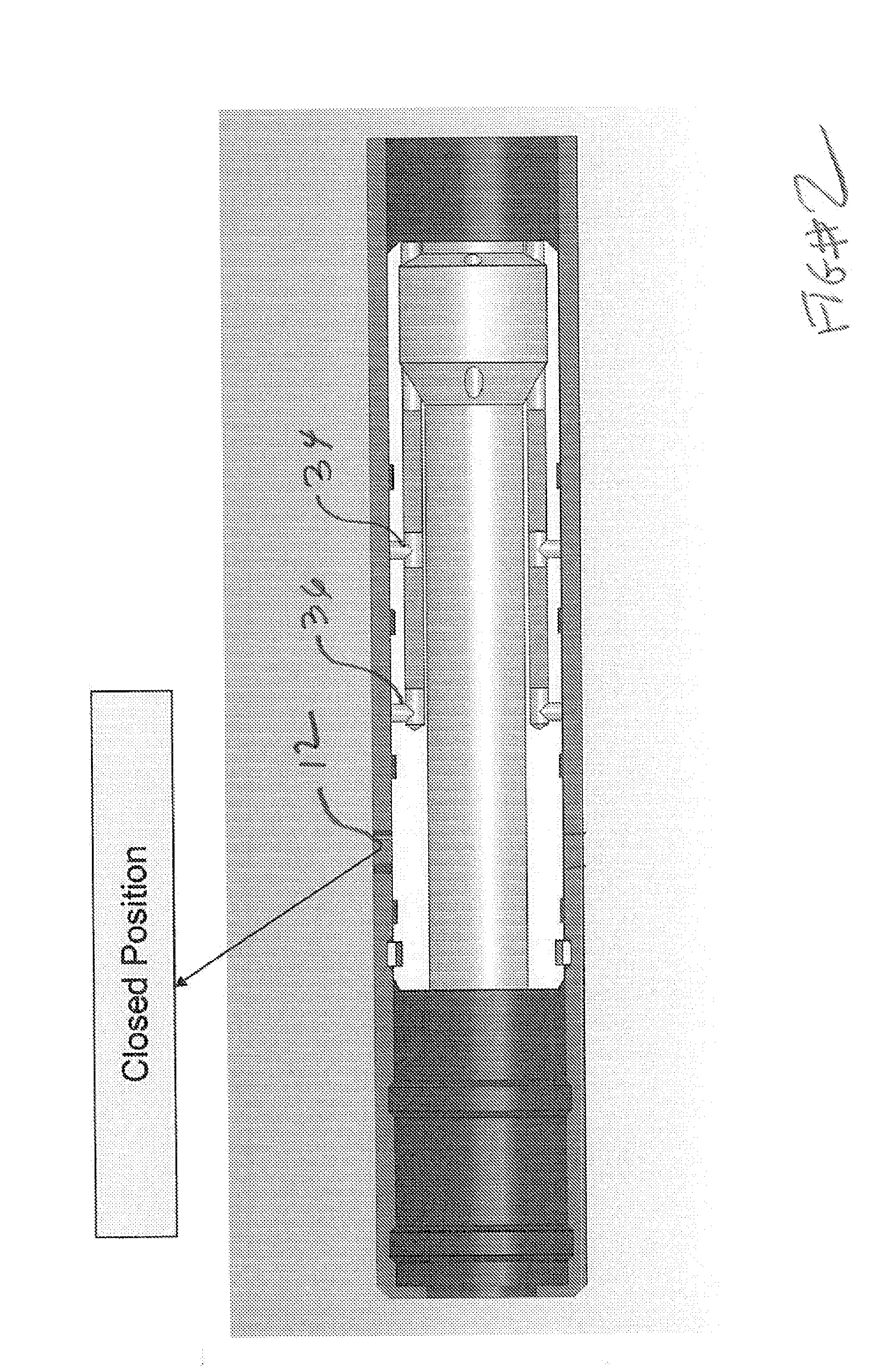
[0009]FIG. 1 illustrates schematically a portion of a tubular string 10 that has at least one but preferably a plurality of ports 12 only one of which is shown. A valve assembly 14 has a through passage 16 and an internal recess 18 where it may be grasped by a tool such as a wireline running tool schematically illustrated by arrow assembly 20. Associated with each port 12 along the tubular string 10 is a unique profile that allows the assembly 14 to be deployed in the positions shown in the FIGS. for initial string makeup and for subsequent manipulation when in the well using the schematically represented tool 20.

[0010]One purpose of associating a valve assembly 14 with a port 12 in a zone in the wellbore is to try to balance flow among the ports 12 regardless of the direction through those ports. When in the FIG. 1 or 3 positions the valve 14 can operate as an injection valve or a production valve. While two open positions are illustrated additional positions for flow are contempla...


PUM


Abstract

One or more valves can be run into a string to land near associated ports in the string for injection or/and production service. When multiple valves are installed they can be initially configured to balance flow into or from a zone. The position of each valve can be altered without removal from the string preferably by a wireline shifting tool. One or more valves can also be removed and replaced when worn preferably using a wireline run tool. The valves can come with an integral sand control feature to facilitate production. Sensors to monitor well conditions and to transmit data to the surface can also be incorporated into the valve module.

Description

FIELD OF THE INVENTION[0001]The field of this invention is downhole systems that allow injection of fluids into the formation and / or production and more specifically valve systems that can balance flows over a zone or multiple zones with the added features of being adjustable while downhole, prevent intrusion of formation sand on down cycles and removable without pulling the string out of the hole.BACKGROUND OF THE INVENTION[0002]Injection is a process of sending water or steam, for example, into a well bore to stimulate production in an adjacent well bore. In some well bores multiple zones may be present which present problems of metering the desired quantities of injected fluids into the individual zones from a single tubing or casing string. Injection can require high pressures and flow rates, which means it generally involves high fluid velocities. High fluid velocities are detrimental to equipment such as valves through which the injected material is pumped. Some procedures tak...

Claims


Application Information

Patent Timeline
IPC IPC(8): E21B34/06E21B43/00
CPCE21B34/14E21B2034/007E21B43/08E21B2200/06
Inventor RICHARD, BENNETT M.JOHNSON, MICHAEL H.
Owner BAKER HUGHES INC
Why Eureka
Try Eureka