Cooling apparatus

Inactive Publication Date: 2005-03-10
SUGITO HAJIME +2
View PDF7 Cites 2 Cited by
  • Summary
  • Abstract
  • Description
  • Claims
  • Application Information

AI Technical Summary

Benefits of technology

[0009] The invention was made in view of the above situation and an object thereof is to provide a cooling apparatus boiling and condensing refrigerant which can facilitate the production of the compo

Problems solved by technology

In this construction, the dimensional accuracy needs to be strictly controlled, for the tubes and holes in the refrigerant container into which the tubes are inserted, in order to prevent the leakage of the refrigerant, this causing a problem that the production of the components becomes difficult.
In addition, as a construction needs to

Method used


Image

  • Cooling apparatus
  • Cooling apparatus
  • Cooling apparatus

Examples


Example

[0094] (First Embodiment)

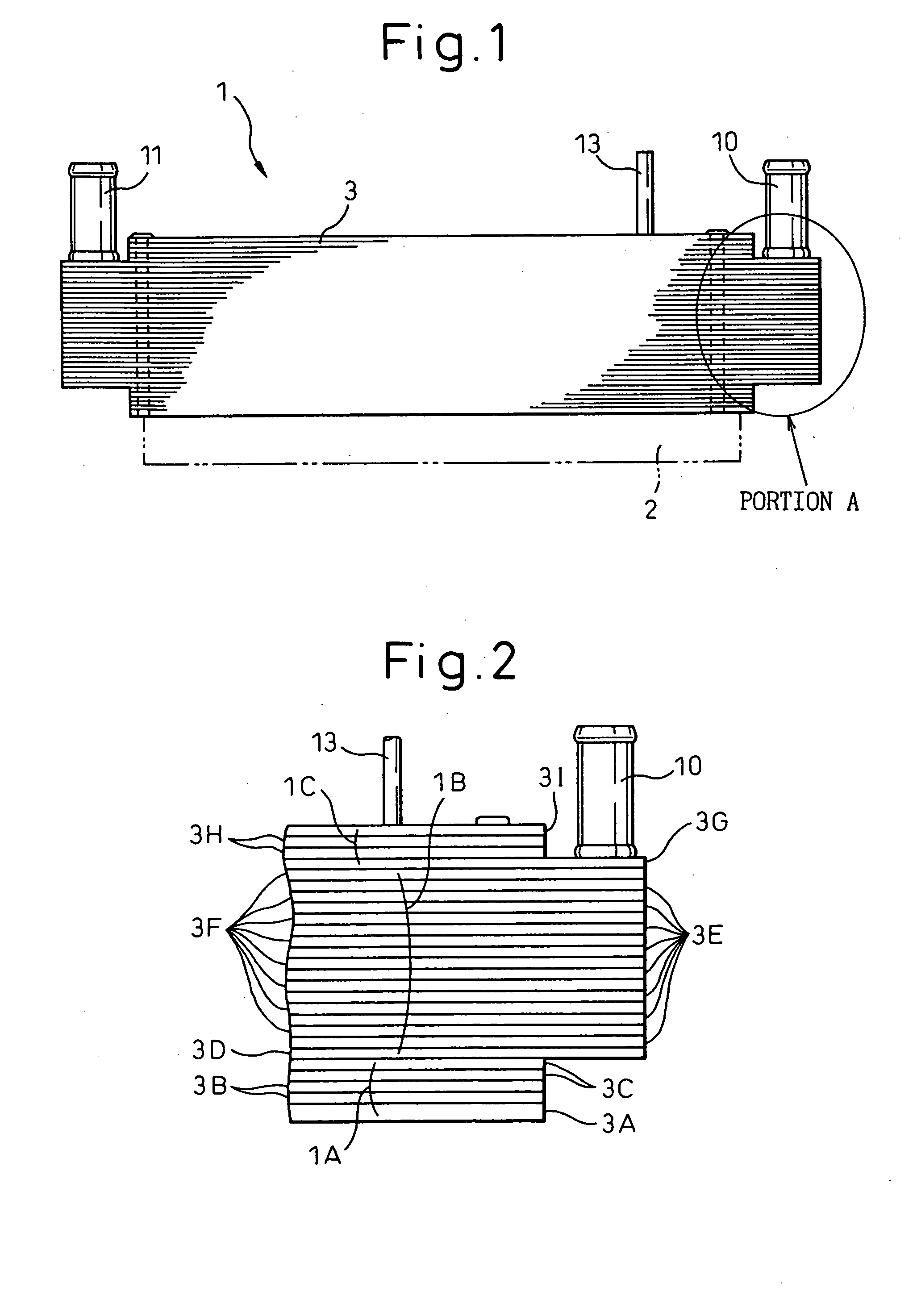
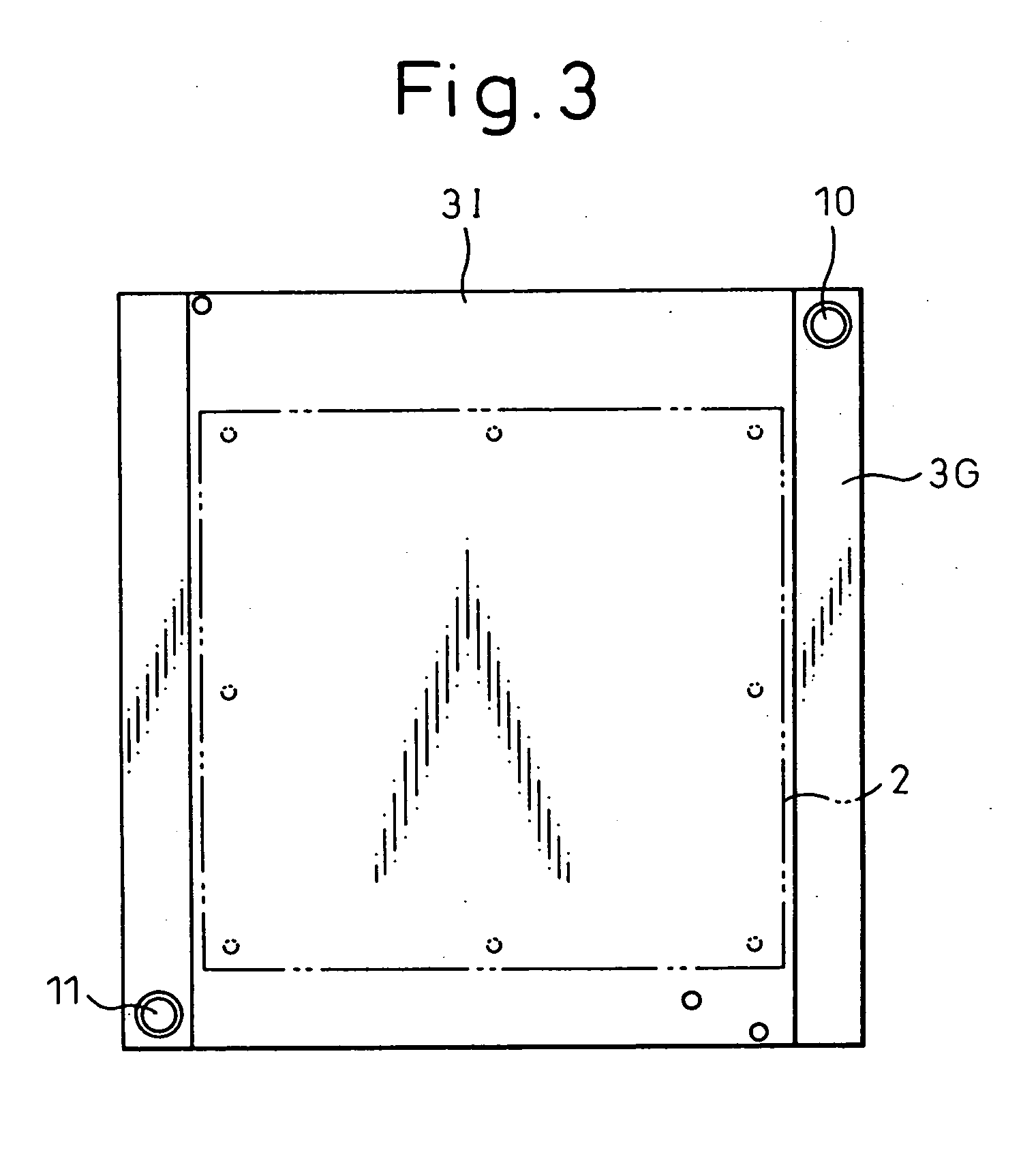
[0095]FIG. 1 is an overall side view of a cooling apparatus 1, FIG. 2 is an enlarged view of a portion A in FIG. 1, and FIG. 3 is a top plan view of the cooling apparatus.

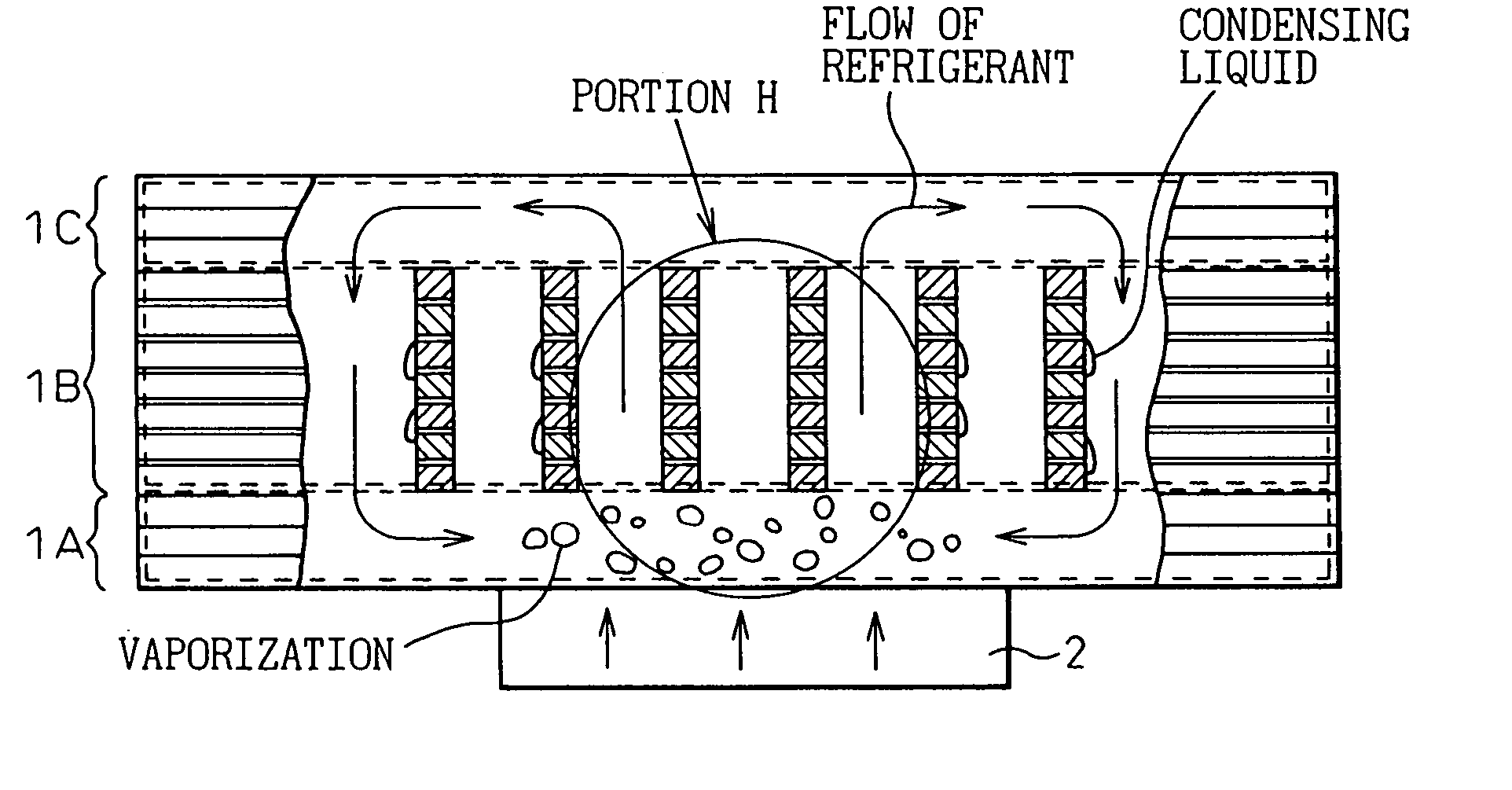
[0096] The cooling apparatus 1 boiling and condensing refrigerant according the first embodiment has provided therein a refrigerant tank portion 1A for storing therein a refrigerant, a heat exchanging portion 1B for executing heat exchange between the refrigerant, that boils by being heated by heat generated from a heat generating element 2 in the refrigerant tank portion 1A, and a cooling medium, and a refrigerant diffusing portion 1C for diffusing the vaporized refrigerant flowing thereinto from the refrigerant tank portion 1A via the heat exchanging portion 1B (refer to FIG. 2 for those constituent portions that have been just described), and, as shown in FIG. 1, has a stacked construction formed by stacking a plurality of pressed members (plate-like members of the invention).

[0097] T...

Example

[0127] (Second Embodiment)

[0128] A second embodiment is an example in which inner fins 14 are inserted in both or either of refrigerant passages and cooling water passages formed in a heat exchanging portion 1B.

[0129]FIG. 10 shows an example in which inner fins 14 are inserted into the cooling water passages (second openings 6), and FIG. 11 shows an example in which inner fins 14 are inserted into the refrigerant passages (first openings 5). The heat conducting surface area can be expanded with the inner fins 14 to thereby improve the cooling performance of the cooling apparatus.

[0130] In addition, for example, as shown in FIGS. 12 and 13, the inner fins 14 may be formed into configurations having an elasticity. As this occurs, in inserting the inner fins 14 into the refrigerant passages or the cooling water passages, as the inner fins 14 can be inserted while being compressed, there is no risk that the inner fins 14 are hooked at intermediate positions along the length of the pa...

Example

[0131] (Third Embodiment)

[0132]FIG. 14 shows plan views of pressed members 3E, 3F.

[0133] A third embodiment describes an example in which the configurations of first openings 5, which form refrigerant passages in the pressed members 3E, 3F which are used in a heat exchanging portion 1B, will be discussed.

[0134] While the first openings 5 in the first embodiment are formed into the elongated hole-like configuration (refer to FIG. 5), first openings 5 in this third embodiment will be formed into a group of opening holes which is constituted by a number of circular holes 5a (alternatively, a number of rectangular holes may be used).

[0135] According to this construction, when compared with the first embodiment, as the condensing surface area of the heat exchanging portion 1B is increased due to an increase in the number of the pillar portions 3C which divide the first openings 5 into the number of circular holes 5a, the cooling performance can be increased.

[0136] In addition, accor...


PUM


Abstract

A cooling apparatus 1 boiling and condensing refrigerant is constructed to have a stacked construction by stacking a plurality of pressed members 3 and comprises a refrigerant tank portion, a heat exchanging portion and a refrigerant diffusing portion.
First openings for passing refrigerant and second openings for passing cooling water are formed in the pressed members 3 used for the heat exchanging portion and the first openings communicate with internal spaces formed in the refrigerant tank portion and the refrigerant diffusing portion. According to the construction, as the cooling apparatus has the stacked construction, tubes and fins that constitute a conventional heat dissipating portion can be eliminated.

Description

CROSS-REFERENCE TO RELATED APPLICATIONS [0001] This application is a divisional of U.S. patent application Ser. No. 10 / 213,804 filed on Aug. 6, 2002. This application claims the benefit of JP 2001-238962, filed Aug. 7, 2001; JP 2002-028614, filed Feb. 5, 2002; and, JP 2002-174340, filed Jun. 14, 2002. The disclosures of the above applications are incorporated herein by reference.BACKGROUND OF THE INVENTION [0002] 1. Field of the Invention [0003] The present invention relates to a cooling apparatus for cooling a refrigerant, that boils when receiving heat from a heat generating element, through heat exchange between the boiling refrigerant and a cooling medium. [0004] 2. Description of the Related Art [0005] For example, a cooling apparatus boiling and condensing refrigerant is known for cooling an inverter which conducts a large amount of electric current for operating a vehicle. This cooling apparatus contains a refrigerant container for storing therein liquid refrigerant and a hea...

Claims


Application Information

Patent Timeline
IPC IPC(8): F28F13/12F28D1/053F28D9/00F28D15/02F28F3/08H01L23/427H05K7/20
CPCF28D9/0075F28F3/086F28D15/02F28F2250/102
Inventor SUGITO, HAJIMEOSAKABE, HIROYUKIOKOCHI, TAKAKI
Owner SUGITO HAJIME
Why Eureka
Try Eureka