
Transmission synchromesh and thrust piece of a transmission synchromesh

a transmission synchromeh and thrust piece technology, applied in the field of transmission synchromeh, can solve problems such as particularly active friction, and achieve the effect of improving transmission synchromeh and increasing transmission synchromeh reliability

Inactive Publication Date: 2008-12-11
HOFER PDC
View PDF12 Cites 14 Cited by
  • Summary
  • Abstract
  • Description
  • Claims
  • Application Information

AI Technical Summary

Benefits of technology

[0020]Desirably, minimizing the space of a pressure element not functionally occupied may improve a transmission synchromesh. In embodiments of the invention, it may be possible to manufacture a pressure element in a material saving manner. By minimizing the space, the remaining synchromesh components of the transmission synchromesh may be designed stronger, thicker or more powerful since they need not give up any additional space required for free movement of space request for the pressure element, i.e., such as the space for the swing-folding-longitudinally or rotationally moveable to allow the pressure element to move properly therewithin. Furthermore, it is desirable to increase the reliability of the transmission synchromesh not only through the configuration of the individual components, but also to guarantee the reliability functionally.
[0021]A transmission synchromesh in accordance with embodiments of the invention is configured in such a manner that gear jumping, i.e., spontaneous disengagement of a gear, is desirably avoided. In other embodiments, shifting rail detents are omitted, and the concomitant minimization of the costs of the transmission are obtained. Of further desire, the occurrence of noises should be preferably low and vibrations minimized. In still other embodiments, the improvement of the efficiency of the transmission may be achieved by avoiding unintentional contacts between the friction surfaces. Including, for instance, the known phenomenon of counter-synchronization when disengaging gears. In this respect, it is desirable to increase tolerance train of the constituent parts within a transmission
[0022]In accordance with certain embodiments of the invention, a transmission synchromesh is provided that includes a pressure element coupled to a synchronizing ring, and one shift sleeve, wherein the pressure element for detent permits an axial position displacement of the shift sleeve relative therewith and contributes to the increased reliability of a transmission.

Problems solved by technology

Especially with conventional designs of annular spring, a phenomenon which occurs as the friction becomes particularly active.

Method used


Image

  • Transmission synchromesh and thrust piece of a transmission synchromesh
  • Transmission synchromesh and thrust piece of a transmission synchromesh
  • Transmission synchromesh and thrust piece of a transmission synchromesh

Examples


Embodiment Construction

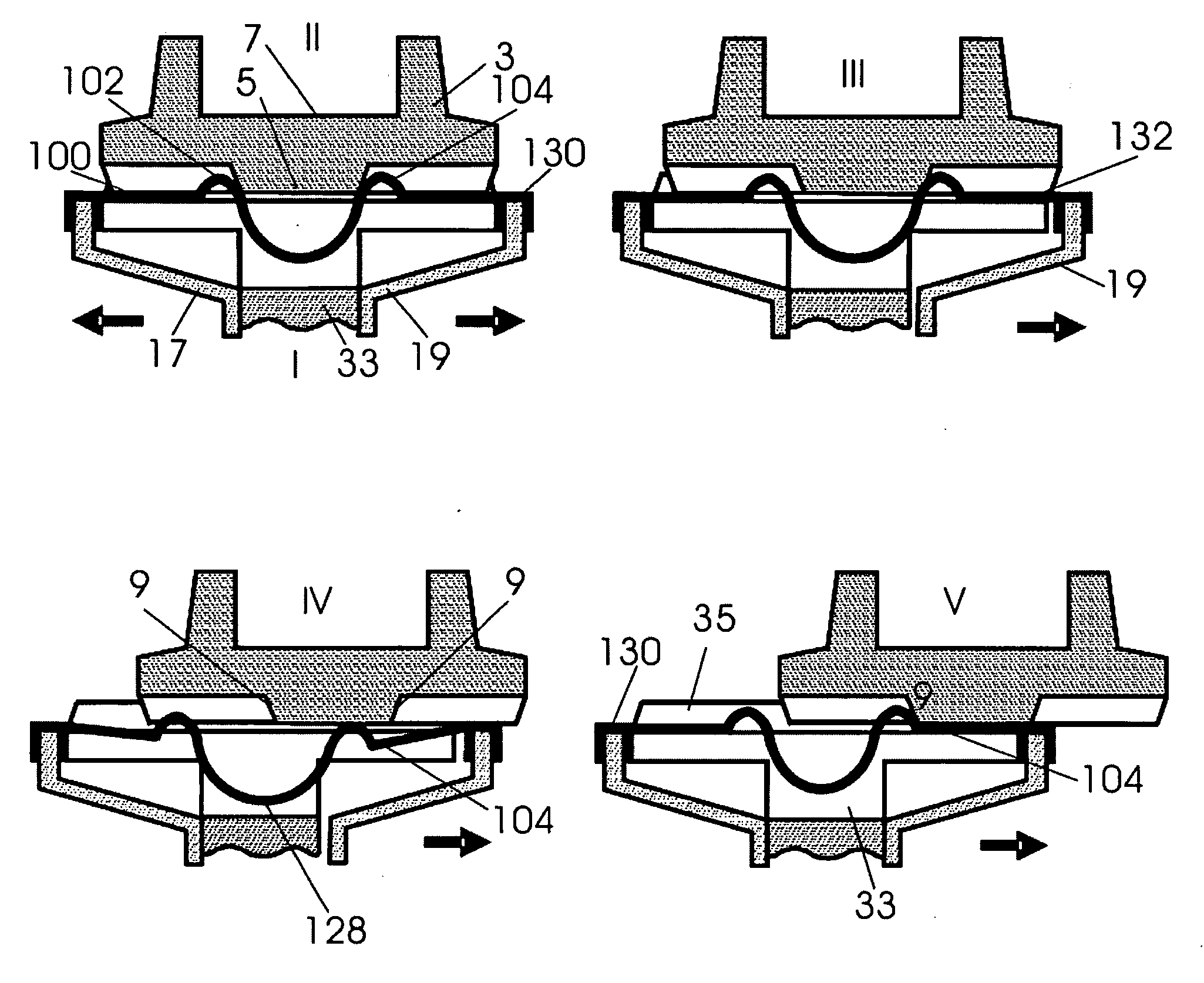
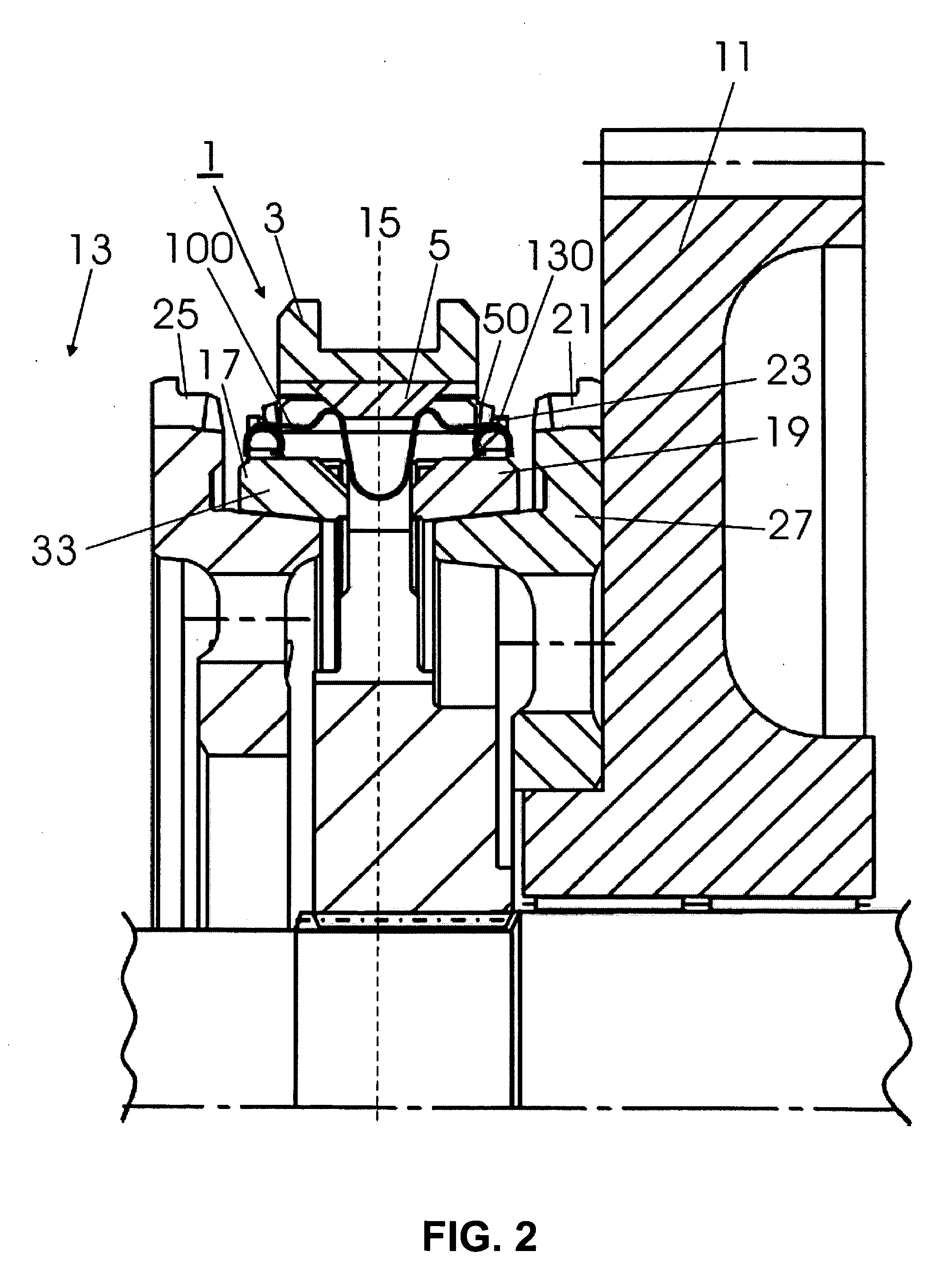
[0065]In the following, the same or similar reference symbols have been selected for similar or same parts between the different embodiments and developments, wherein partly reference numbers numbered higher by 100 in each case have been selected for the various embodiments of similar parts of a pressure element in spring-like embodiment according to the invention.

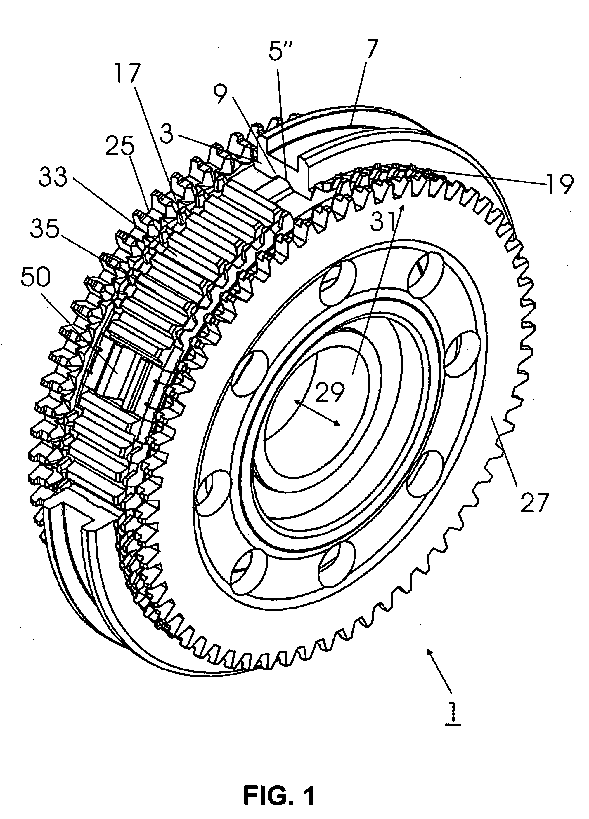
[0066]FIG. 1 shows important components of a transmission synchromesh unit 1, wherein for simplification further components such as for instance the two loose gears 11, 13 and a central shaft have been omitted. The round transmission synchromesh unit 1 is limited to the outside by a shift sleeve 3 which in the example shown is a slide sleeve. The shift sleeve 3, which extends over 360 degrees of an angular dimension, is shown cut over approximately 90 degree of its length so that below the shift sleeve 3 a synchronizer 33 is visible on whose surface a synchronizer external toothing 35 is provided which may detent in the sh...


PUM


Abstract

A transmission synchromesh is provided that includes a pressure element coupled to a synchronizing ring, and one shift sleeve, wherein the pressure element for detent permits an axial position displacement of the shift sleeve relative therewith. A pressure element and a transmission synchromesh method for improved synchronization are also provided.

Description

PRIORITY CLAIM[0001]This application claims the benefit of the filing date of German priority application DE 10 2007 025 022.5, filed May 28, 2007, for “TRANSMISSION SYNCHROMESH AND THRUST PIECE OF A TRANSMISSION SYNCHROMESH,” the contents of the entirety of which is incorporated herein by this reference.TECHNICAL FIELD[0002]The present invention relates to transmission synchromesh, more particularly, to a synchronizing ring synchromesh with an underlying spring or pressure element. The pressure element, i.e., the spring, improves synchronization by performing additional functions. The invention also relates to a novel spring for a synchromesh according to embodiments of the invention.BACKGROUND[0003]With respect to the design of a conventional transmission structure, exemplary reference can be made to the technical documentation of Volkswagen AG relating to the six-speed manual transmission 08D. Furthermore, a widely known synchromesh of similar conventional design can be found in ...

Claims


Application Information

Patent Timeline
IPC IPC(8): F16D23/08
CPCF16D23/06
Inventor STEINZ, JANINAKALMBACH, KLAUSSCHEIHING, HARALD
Owner HOFER PDC
Learn More