Blank For an Axle Beam, Wheel Suspension Comprising an Axle and a Method For Manufacturing an Axle

a technology of axle beams and axles, which is applied in the direction of wheel-axle combinations, steering links, transportation and packaging, etc., can solve the problems of increasing handling costs, difficult to configure rods and fastenings with sufficient precision, and increasing the difficulty of changing a decision. , to achieve the effect of reducing the risk of tilting, good stability and good precision

Inactive Publication Date: 2008-12-11
VOLVO LASTVAGNAR AB
View PDF11 Cites 10 Cited by
  • Summary
  • Abstract
  • Description
  • Claims
  • Application Information

AI Technical Summary

Benefits of technology

[0005]According to an aspect of the invention, a continuous blank, made in one piece, is used, which at each end has a bushing, comprising a bearing for a kingpin, and lug-shaped protrusions situated on each side of a plane through the longitudinal axes of said bushings. The lug-shaped protrusions have a first part, which, following machining of the lug-shaped protrusion, is suitable for use as a locking surface for a wheel-spindle, should the axle beam be used to support a fixed, non-steerable wheel axle, and that said lug-shaped protrusions have a second part, which is suitable for use as an end stop for limiting the deflection of the rotary motion of a wheel spindle after the lug-shaped protrusion is at least partially machined away, should the axle beam be used to support a steerable wheel axle. The same blank is therefore used for both steered and non-steered wheel axles. By machining is meant that material removes from the integrally made blank. Machining can be realized, for example, by milling, boring and grinding. Both the end stops for deflection limitation alternatively locking surfaces for the wheel spindle can thereby be formed from the lug-shaped protrusion. The fact that the locking surface is situated directly on the beam and is formed integrally therewith means that the wheel can be locked with good stability. In addition, machining can be realized with good precision, whereby the risk of tilting is reduced compared to if locking is realized via a rod.
[0006]In general terms, this can be explained by the fact that it is easier to achieve good accuracy if fewer components interact, since, with fewer components, the overall error tolerance is reduced. In addition, the placement of the surfaces which constitute end stops can be easily adapted to different requirements in respect of different vehicles, since the machining of the lug-shaped protrusion can then easily be adapted such that a different amount of material is machined away, in which case the end stop will be placed in the desired location. For the purpose of providing a locking surface, alternatively an end stop, the lug-shaped protrusion has a first part, which, following machining of the lug-shaped protrusion, is suitable for use as a locking surface, and a second part, which is suitable for use as an end stop for limiting the deflection of a rotary motion of a wheel spindle.
[0009]In order easily to achieve locking between wheel spindle and axle beam, a locking surface of the first part is preferably placed beyond the center point, in the longitudinal direction of the axle beam, of a longitudinal axis of the bushing constituting a bearing for the kingpin.

Problems solved by technology

This means that two sets of blanks for axle beams must be stocked, which adds to the handling costs.
In addition, it is more complicated to change a decision on the extent to which the axle beam shall be configured with fixed or steered wheel axle.
The hitherto known solution has drawbacks in that a plurality of joints need to be provided and in that it is difficult to configure rod and fastening with sufficient precision, which means that the wheel can come to be set somewhat obliquely, possibly leading to increased fuel consumption.
The known solutions have exhibited drawbacks as a result of the construction having become heavy, expensive and bulky, nor was it well matched to its unique application.
Since the position of the wheels could not easily be set with sufficient precision, known solutions have sometimes caused unnecessary tire wear as a result of incorrect mounting of the wheels.

Method used


Image

  • Blank For an Axle Beam, Wheel Suspension Comprising an Axle and a Method For Manufacturing an Axle
  • Blank For an Axle Beam, Wheel Suspension Comprising an Axle and a Method For Manufacturing an Axle
  • Blank For an Axle Beam, Wheel Suspension Comprising an Axle and a Method For Manufacturing an Axle

Examples


Embodiment Construction

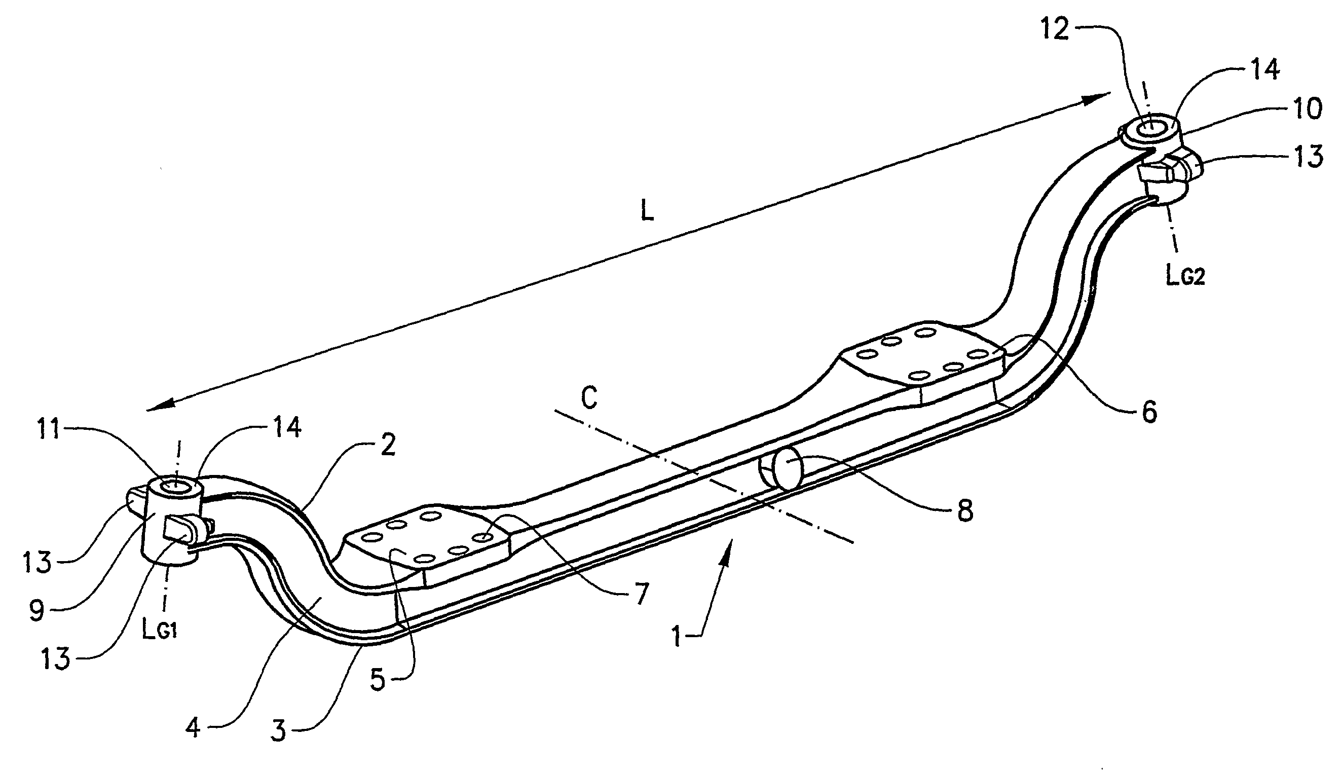
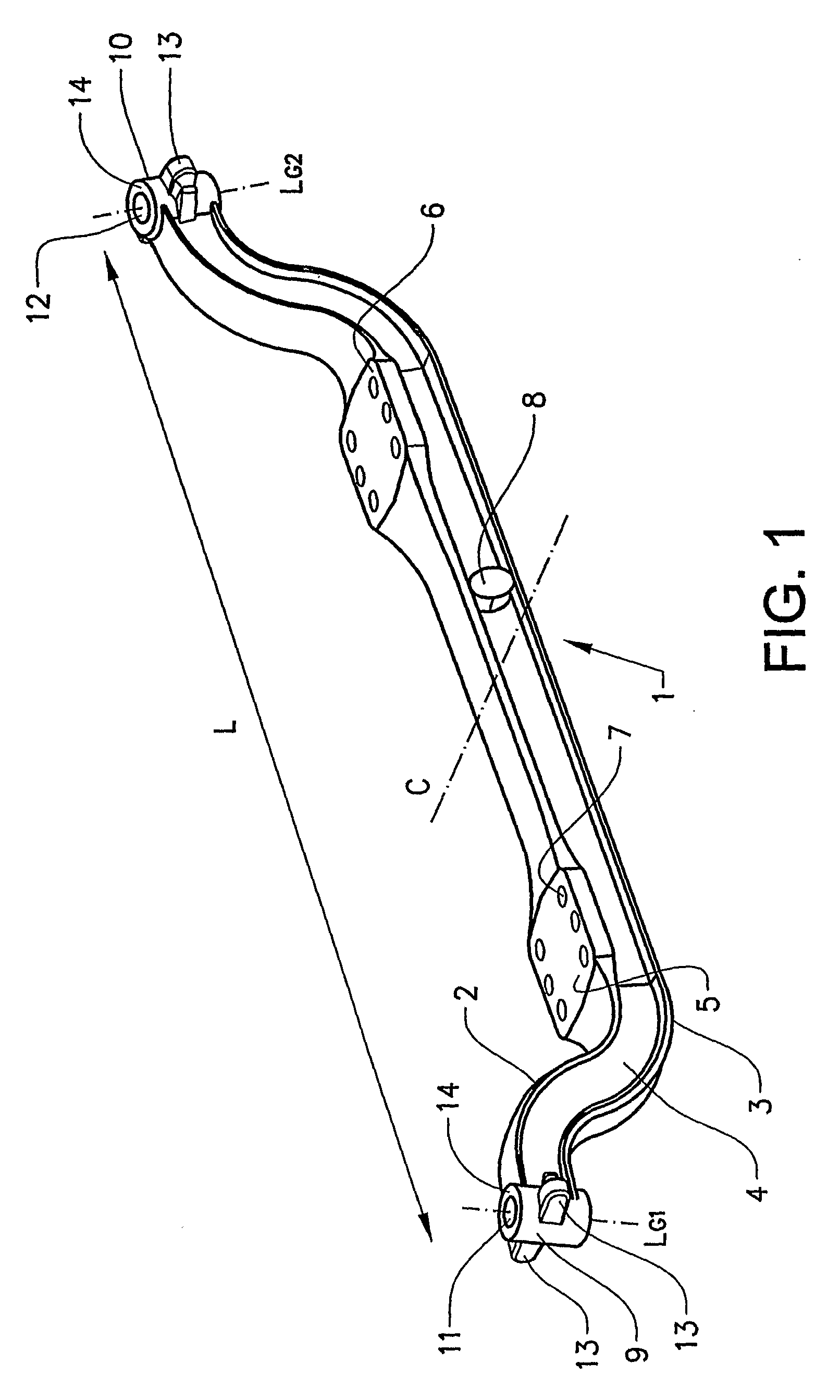
[0022]In FIG. 1 is shown a blank 1 for an axle beam intended to support a wheel axle. The blank for the axle beam 1 extends in a substantially longitudinal direction L and has an upper and a lower flange 2, 3, which flanges extend in the longitudinal direction and are connected by a rib 4. The axle beam can conventionally be straight or have an extent in a plane through the rib which deviates from a straight beam, for example somewhat U-shaped as in the illustrative embodiment shown. Deviation from a straight axle beam is used in order easily to vary the frame height of the vehicle to which the axle beam is fitted. The axle beam also has fastening surfaces 5, 6, which are intended to be fastened to a beam structure present in a vehicle. The fastening surfaces have bushings 7, intended for the fitting of fastening elements for fastening the axle beam to a beam structure of a vehicle. In addition, in the embodiment shown, close to a midpoint C, with respect to the longitudinal directi...


PUM


Abstract

A blank for an axle beam intended to support a wheel axle is formed from a continuous piece and, at its respective ends, has, on the one hand, a bushing constituting a bearing for a kingpin for supporting a wheel spindle and, on the other hand, lug-shaped protrusions on each side of the bushing, and a wheel axle made from such a blank. The invention can provide a blank which is suitable both for steerable and non-steerable wheel axles for vehicles.

Description

BACKGROUND AND SUMMARY[0001]The present invention relates to a blank for an axle beam, a wheel suspension, and a method for manufacturing an axle beam. It especially relates to a blank for an axle beam which is configured so as to be usable for both steerable wheel axles and fixed, non-steerable wheel axles, and to wheel suspensions comprising a machined such blank, and to a method for providing an axle beam from such a blank.[0002]Axle beams are used to support wheel axles in vehicles. In the manufacture of heavy-duty vehicles such as, for example, trucks, high demands are placed upon flexibility for the satisfaction of specific customer requirements, so that the vehicle is adaptable to different applications. For this purpose, vehicles, especially trucks, are manufactured with both steerable wheel axles and non-steerable, fixed wheel axles. An example of such axles which can be configured so as to be both steerable and non-steerable is a non-driven pusher axle in a commercial vehi...

Claims


Application Information

Patent Timeline
Patent Type & Authority Applications(United States)
IPC IPC(8): B60B35/00B60G3/00B60BB60B35/06B60G9/00
CPCB60B35/06B60G9/00B60G2200/44Y10S180/905B60G2300/14B60G2300/38B60G2206/312
Inventor FUKS, LEONSVENSSON, ROLAND
Owner VOLVO LASTVAGNAR AB
Why Eureka
Try Eureka