Bicycle rear suspension system

Active Publication Date: 2008-12-11
IND RAD
View PDF18 Cites 58 Cited by
  • Summary
  • Abstract
  • Description
  • Claims
  • Application Information

AI Technical Summary

Benefits of technology

[0011]There is further provided, in accordance with another aspect of the present invention, a method of improving riding performance of a bicycle having a main frame and a rear wheel suspension system including a rear stay member pivotally attached to the main frame by upper and lower link members and a shock absorber mounted between the main frame and the upper link member, a rear wheel of the bicycle rotating about a rear wheel axle mounted to the rear stay member, the method comprising the steps of: defining an average chain torque line of the rear wheel suspension system by determining an average of a number of possible chain torque lines extending along a tension side of a chain when the chain of the bicycle when positioned on chain sprockets of the bicycle; defining an upper axis extending

Problems solved by technology

Unwanted suspension movement resulting fr

Method used


Image

  • Bicycle rear suspension system
  • Bicycle rear suspension system
  • Bicycle rear suspension system

Examples


Embodiment Construction

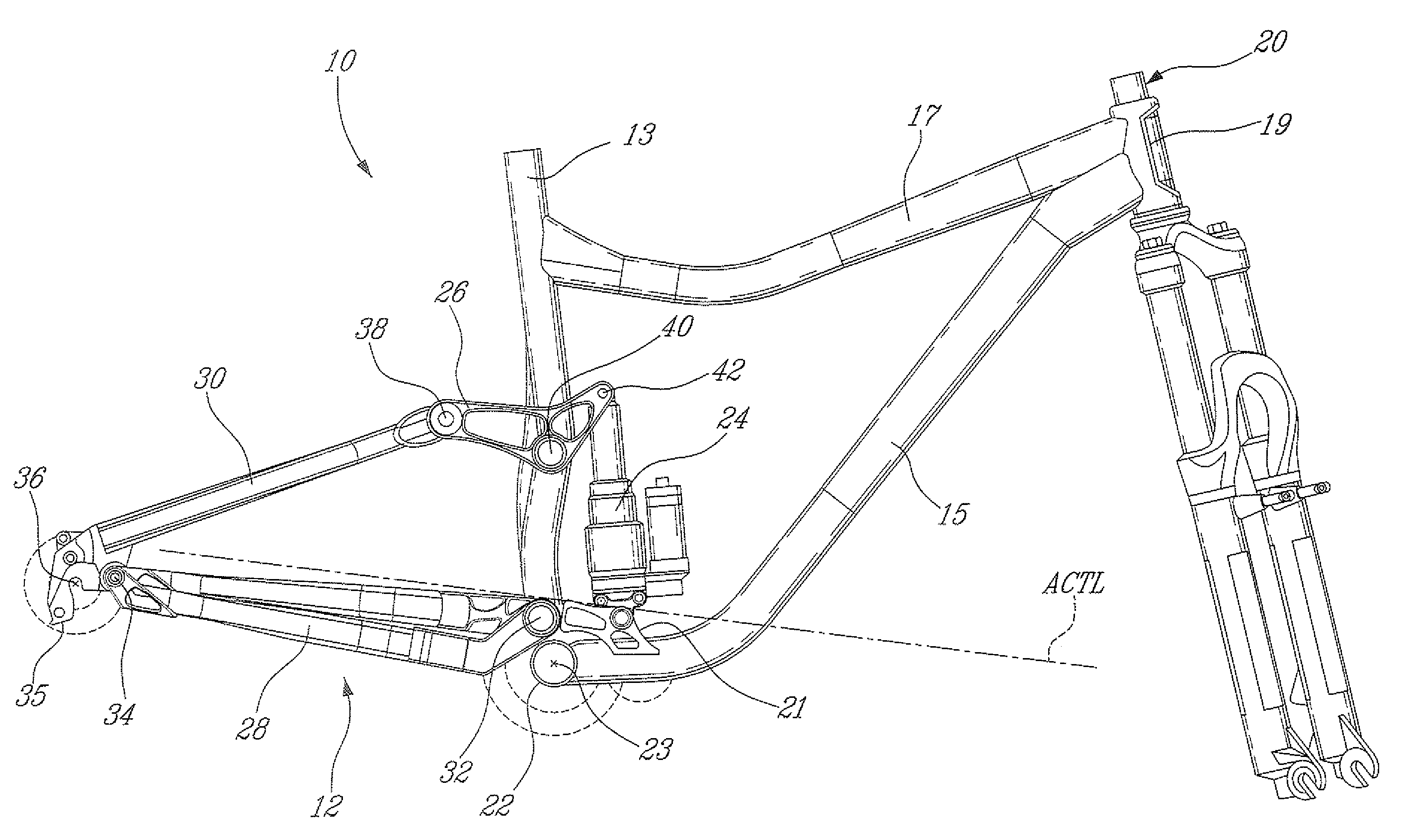
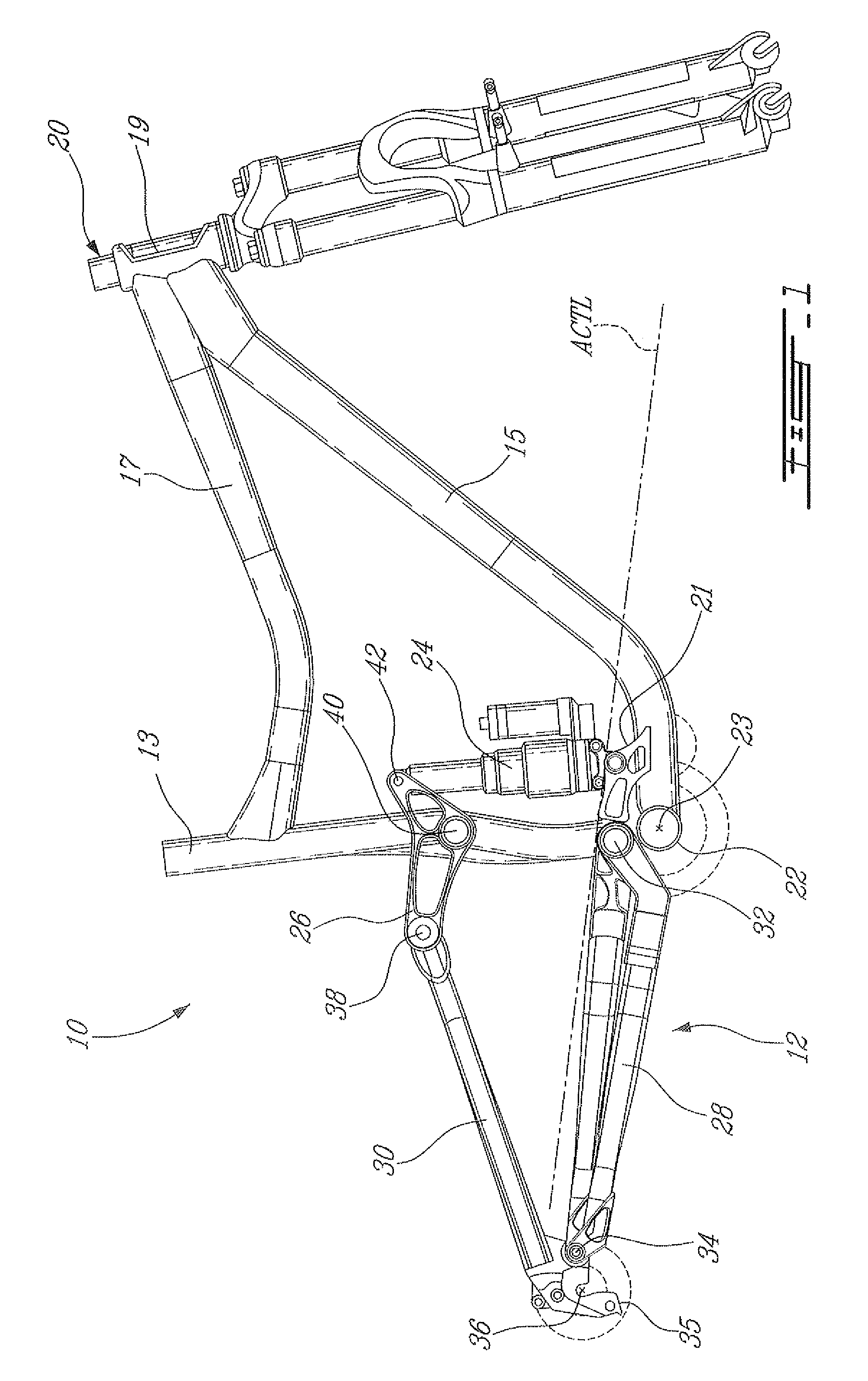
[0021]Referring to FIG. 1, a bicycle frame assembly according to a particular embodiment of the present invention is generally shown at 10, and comprises a rear suspension system linkage assembly 12 and a main frame 20. In a particular embodiment, the main frame 20 is manufactured out of aluminum, steel, carbon-fiber, or any other adequate material.

[0022]The main frame 20 comprises a seat tube 13, a down tube 15, a top tube 17, a head tube 19, and a bottom bracket 22. The bottom bracket 22 defines a crank axis 23 therethrough, about which the bicycle's pedal cranks rotate. In the embodiment shown, the seat tube 13 rigidly connects the bottom bracket 22 and the top tube 17. In an alternate embodiment, the seat tube 13 is of “partial length”, i.e. rigidly suspended only from one of the tubes such as the top tube 17, for example.

[0023]In an alternate embodiment, the main frame 20 is a single large structure rather than the aforementioned assembly of distinct tubes, such as a monologue-...


PUM

PropertyMeasurementUnit
Fractionaaaaaaaaaa
Fractionaaaaaaaaaa
Fractionaaaaaaaaaa

Abstract

A bicycle rear wheel suspension system includes an upper link and a lower link both pivotally attached to the frame and to a rear stay member. An instantaneous center of rotation of the rear stay member is defined at an intersection between an upper axis extending through first and second pivots of the upper link and a lower axis extending through third and fourth pivots of the lower link. Throughout a travel distance of a shock absorber of the suspension system, the instantaneous center of rotation remains below an average chain torque line of the bicycle, the lower axis remains above an axle axis extending through the rear wheel axle, and a portion of the lower axis defined between the third and fourth pivots extends below the average chain torque line.

Description

CROSS-REFERENCE TO RELATED APPLICATIONS[0001]The present application claims priority on U.S. Provisional Patent Application No. 29 / 942,537, filed Jun. 7, 2007, the entire contents of the specification of which is incorporated herein by reference.TECHNICAL FIELD[0002]The present invention relates generally to two-wheeled vehicles, particularly bicycles, and more specifically to a rear wheel suspension for such bicycles.BACKGROUND ART[0003]Rear wheel suspension systems have been used on a variety of two-wheeled vehicles, including motorcycles, scooters and bicycles, for providing improved rider comfort and increased performance.[0004]Rear wheel suspensions on pedal powered bicycles have become increasingly popular, and generally provide a rider with the benefits of a more comfortable ride and better control over the bicycle. Such bicycle suspension systems improve ride quality by absorbing the energy incurred from encountering ground obstacles, rather than transmitting them through th...

Claims


Application Information

Patent Timeline
IPC IPC(8): B62K3/00B62K25/00
CPCY10T29/49904B62K25/286
Inventor O'CONNOR, D'ARCY
Owner IND RAD
Why Eureka
Try Eureka