Rotational speed determination

a technology of rotational speed and determination field, which is applied in the direction of wind motors with perpendicular air flow, mechanical power/torque control, wind energy generation, etc., can solve the problems of clearly defective rotational speed signal behavior of wind power plants and only achieved production accuracy with great effor

Active Publication Date: 2008-12-11
SIEMENS GAMESA RENEWABLE ENERGY SERVICE GMBH
View PDF24 Cites 47 Cited by
  • Summary
  • Abstract
  • Description
  • Claims
  • Application Information

AI Technical Summary

Benefits of technology

[0008]The formed differences or quotients are preferably filtered for the determination of the rotating apparatus speed of the rotating apparatus. The filter, especially, preferab

Problems solved by technology

This production accuracy is only achieved with great effort.
Moreover, there are

Method used


Image

  • Rotational speed determination
  • Rotational speed determination
  • Rotational speed determination

Examples


Embodiment Construction

[0026]In the following figures, the same or similar types of elements or corresponding parts are provided with the same reference numbers in order to prevent the item from needing to be reintroduced.

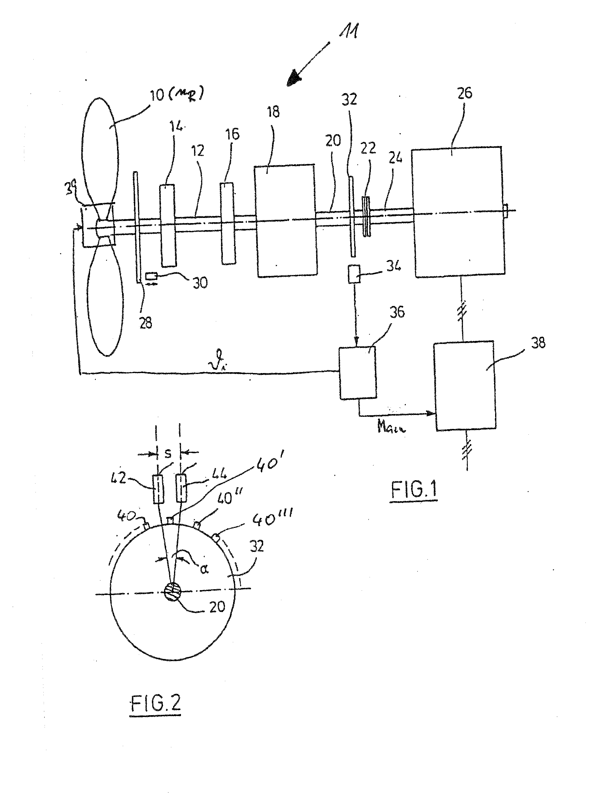
[0027]FIG. 1 shows a rotor 10 of a wind power plant 11, the shaft 12 of which is mounted in two bearings 14, 16. The shaft 12 is the input shaft of a gearbox 18 not described in greater detail, which transmits the rotational speed of the shaft to a higher rotational speed, for example by the factor 100. An output shaft 20 of the gearbox 18 is coupled with a shaft 24 of an alternator 26 via a coupling 22. A locking disk 28 is arranged in a torque-proof manner on the shaft 12, which works together with a locking element 30, between the wind rotor 10 and the first bearing 14. If the locking element 30 is inserted, for example, into an opening or recess in the locking disk 28, the rotation of the shaft 12 is thereby prevented. A transmitter disk 32 is arranged in a torque-proof manner on the...


PUM


Abstract

The invention relates to a method for the operation of a wind power plant (11) with a rotor (10) and a rotating apparatus (20, 22, 24) connected with the rotor (10), wherein a rotor speed (nR) and a rotating apparatus speed (n) are interrelated via a specifiable transmission ratio, wherein the rotating apparatus speed (n) is determined, and wherein a rotational speed measurement value (rpmi) is captured for the determination of the rotating apparatus speed (n). The method according to the invention is characterized in that the rotational speed measurement value (rpmi) is corrected with an intermittently variable correction value (rpmi,c) so that the determined rotating apparatus speed (rpmi,f) results, and wherein the determined rotating apparatus speed (rpmi,f) is fed as the actual value into a regulation apparatus (36) of the wind power plant (11).

Description

BRIEF SUMMARY OF THE INVENTION[0001]The invention relates to a method for the operation of a wind power plant with a rotor and a rotating apparatus connected with the rotor, wherein a rotor speed and a rotating apparatus speed are interrelated via a specifiable transmission ratio, and wherein the rotating apparatus speed is determined, wherein a rotational speed measurement value is captured for the determination of the rotating apparatus speed.[0002]The rotational speed capture is an important component of the control and regulation system of the wind power plant. Within the framework of the invention, a regulation apparatus is also understood in particular as a control apparatus. In order to achieve a fast reaction time, the rotational speed capture takes place on the fast side of the drive train or the output side of a gearbox. A multi-pulse rotational speed measurement is performed. For this, a highly accurately manufactured rotational speed measurement disk or transmitter disk,...

Claims


Application Information

Patent Timeline
IPC IPC(8): F03D7/00G01P3/44
CPCF03D7/042F03D11/0091F05B2260/821F05B2270/327Y02E10/723Y02E10/722F03D17/00Y02E10/72
Inventor KRUEGER, THOMAS
Owner SIEMENS GAMESA RENEWABLE ENERGY SERVICE GMBH
Why Eureka
Try Eureka