
Liquid Crystal Display Device

Active Publication Date: 2008-12-11
PANASONIC LIQUID CRYSTAL DISPLAY CO LTD +1
View PDF16 Cites 50 Cited by
  • Summary
  • Abstract
  • Description
  • Claims
  • Application Information

AI Technical Summary

Benefits of technology

[0010]The techniques disclosed in JP-A-2006-100225 and JP-A-2006-310150 make it possible to diffuse the light vertically in the light source unit 203a and are therefore effective when a linear light source such as a fluorescent lamp is used. However, when a light emitting diode (LED) is used as a light source of the backlight, the vertical mura shown in FIG. 13A can be prevented, but the lateral mura cannot because the LED is a point light source, thus resulting in a problem that striped mura appears on the liquid crystal panel.
[0013]In accordance with the present invention, even if a point light source is used as a light source of the backlight, it is possible to provide a liquid-crystal display device having a diffuser board that does not produce striped mura on the surface of the liquid crystal panel.

Problems solved by technology

However, when a light emitting diode (LED) is used as a light source of the backlight, the vertical mura shown in FIG. 13A can be prevented, but the lateral mura cannot because the LED is a point light source, thus resulting in a problem that striped mura appears on the liquid crystal panel.

Method used


Image

  • Liquid Crystal Display Device
  • Liquid Crystal Display Device
  • Liquid Crystal Display Device

Examples


Embodiment Construction

[0028]The best mode or modes for carrying out the present invention will be explained in detail below with reference to the accompanying drawings as required.

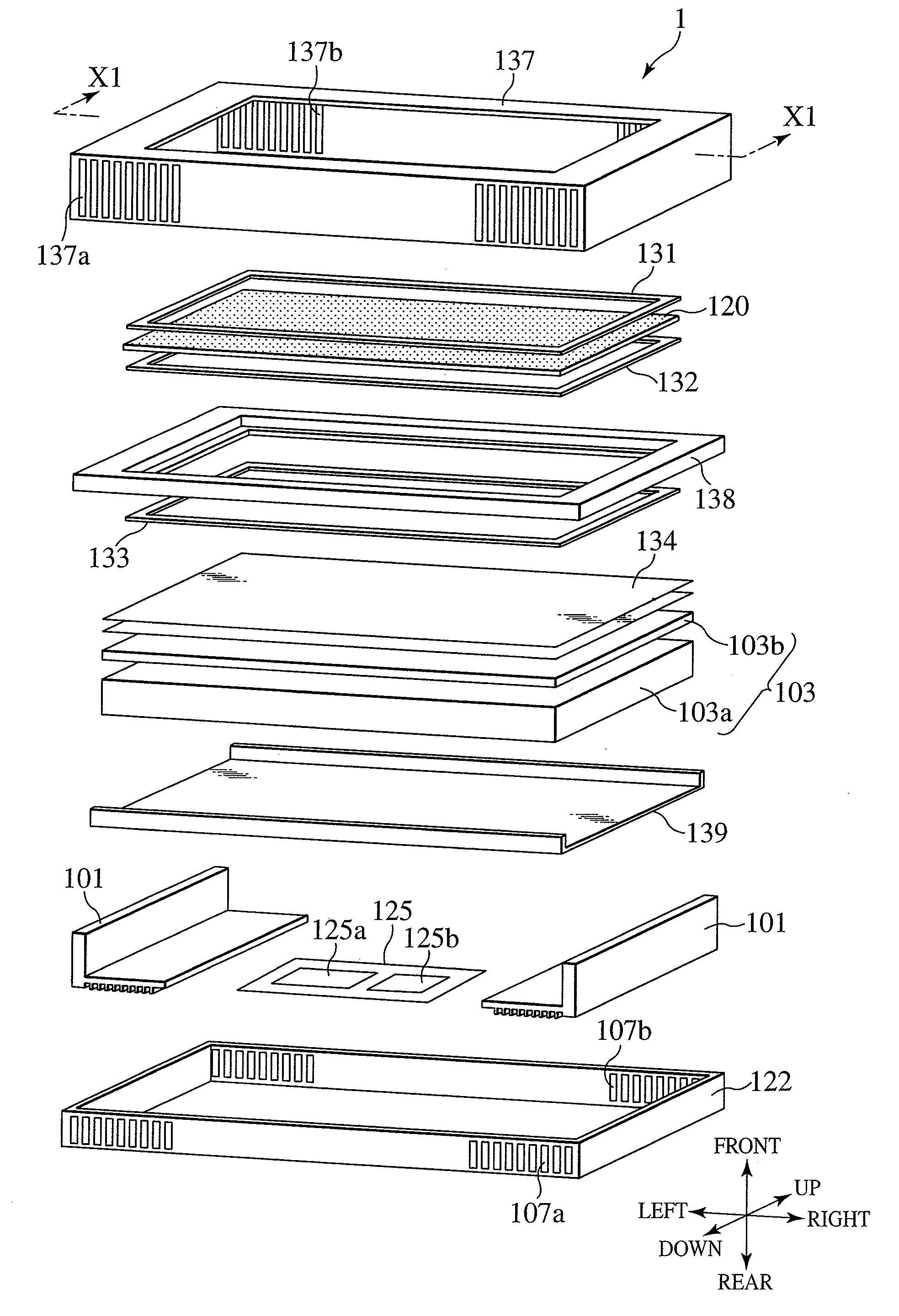
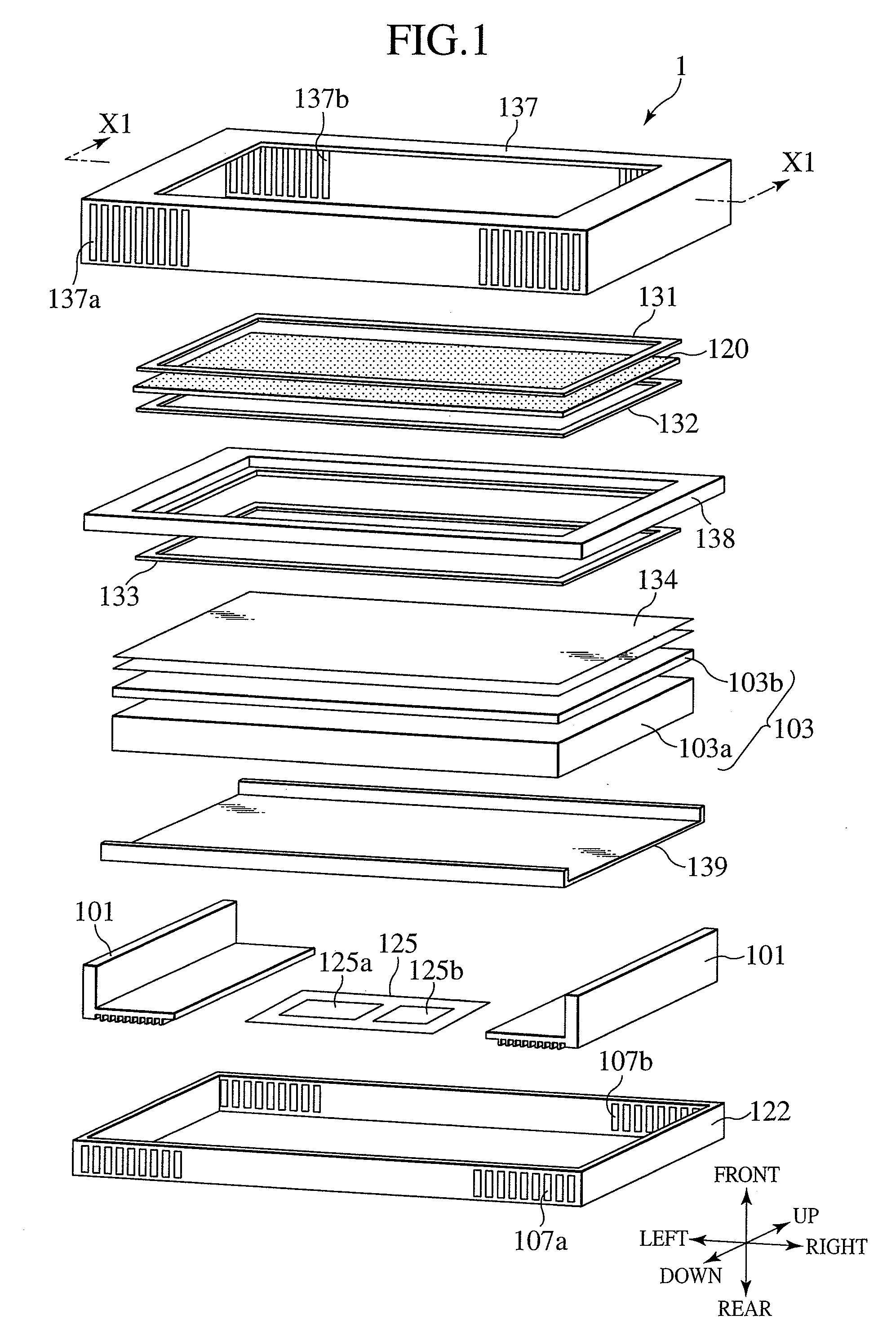
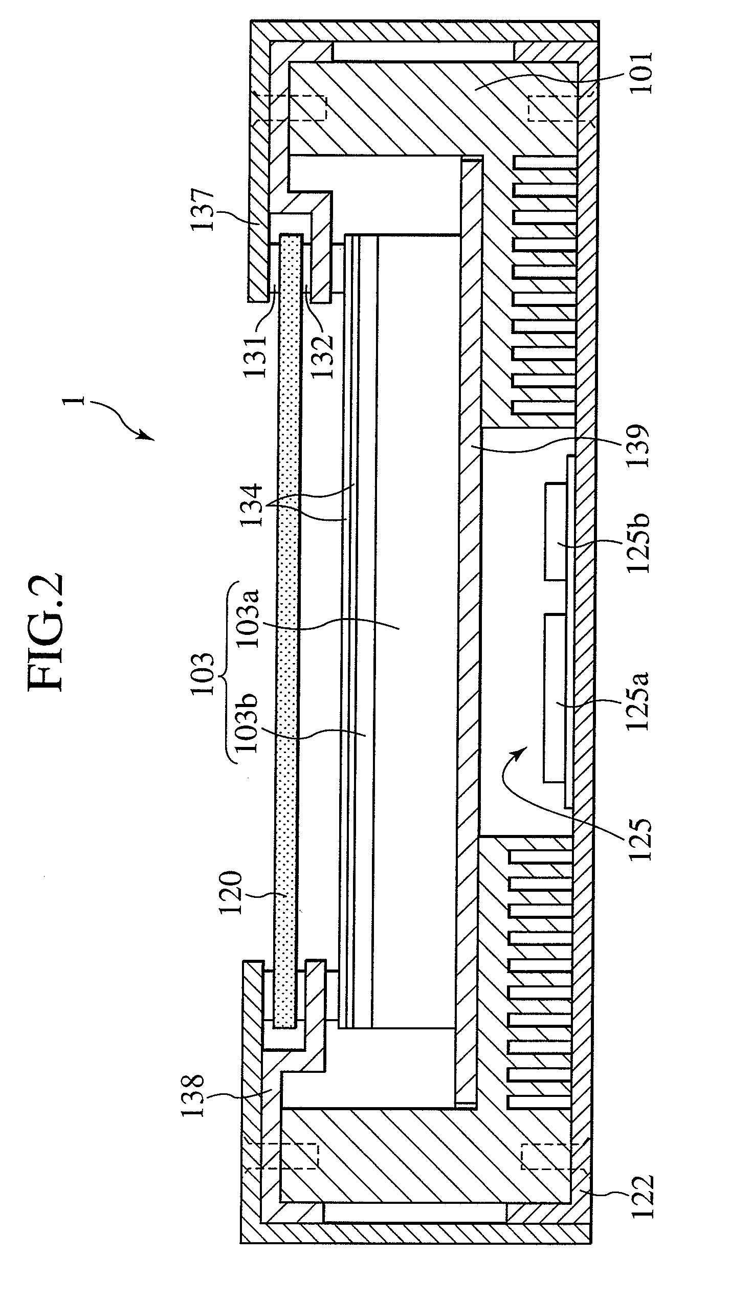
[0029]FIG. 1 is a perspective view of the configuration of a liquid-crystal display device according to the present embodiment; FIG. 2, a cross-sectional view taken along the X1-X1 line of FIG. 1; FIG. 3A, a diagram showing arrangements of wiring and drivers of a liquid crystal panel; FIG. 3B, a diagram showing arrangements of a Thin Film Transistor (TFT) and a pixel electrode; FIG. 4A, a diagram showing a backlight apparatus; FIG. 4B, a diagram showing a LED module; FIG. 5A, a diagram showing the shape of a modified lens; and FIG. 5B, a cross-sectional view taken along the X2-X2 line of FIG. 5A. With the present embodiment, as shown in FIG. 1, the horizontal and vertical directions and the front-back directions are defined with the display screen of a liquid crystal panel 120 as the basis.

[0030]As shown in FIG. 1, a liquid-cry...


PUM


Abstract

An object of the present invention is to provide a liquid-crystal display device which includes a diffuser board that does not produce striped mura on the surface of a liquid crystal panel even if point light sources are used as light sources of a backlight.A backlight apparatus 103 is provided with a diffuser board 103b having diffusion portions 103b1. At each of the diffusion portions 103b1, the light L emitted by a LED module 104 included in a light source unit 103a is reflected by prism patterns P and diffused around the LED module 104. Then, the diffused light is reflected again by a reflecting surface formed on the inner surface of a housing 103c and emitted from the backlight apparatus 103, thereby achieving illuminating light without mura.

Description

BACKGROUND OF THE INVENTION[0001]1. Field of the Invention[0002]The present invention relates to a liquid-crystal display device.[0003]2. Description of the Related Art[0004]In recent years, an increasing number of light-emitting-type plasma display panels and non-light-emitting-type liquid-crystal display devices have been used as display devices instead of Cathode Ray Tubes (CRT).[0005]Of these display devices, a liquid-crystal display device uses a liquid crystal panel as a transmissive light modulation device and includes an illuminating device (also referred to as a backlight) on the back surface of the liquid crystal panel to irradiate the liquid crystal panel with light. The liquid crystal panel forms an image by controlling the transmission of the light emitted from the backlight.[0006]Although the liquid-crystal display device is characterized in that it can be formed more thinly than a CRT, a still thinner liquid-crystal display device has been demanded in recent years. Fo...

Claims


Application Information

Patent Timeline
IPC IPC(8): G02F1/13357
CPCG02F1/133603G02F1/133606G02F1/133611G02F2001/133607G02F2001/133628G02F1/133628G02F1/133607
Inventor SEKIGUCHI, YOSHIFUMIHIYAMA, IKUOKANEKO, HIROKI
Owner PANASONIC LIQUID CRYSTAL DISPLAY CO LTD
Learn More