Optical fiber with large effective area

a technology of optical fiber and effective area, applied in the field of optical fiber, can solve the problems of relative cost of manufacture, and achieve the effect of effective refractive index

Inactive Publication Date: 2008-12-11
CORNING INC
View PDF10 Cites 52 Cited by
  • Summary
  • Abstract
  • Description
  • Claims
  • Application Information

AI Technical Summary

Problems solved by technology

These MDFs provide 6 to 12 ps / nm / km 2 but can have an effective area of no more than 60 μm2, and are relatively expensive to manufacture due to tight tolerance and core design complexity.

Method used


Image

  • Optical fiber with large effective area
  • Optical fiber with large effective area
  • Optical fiber with large effective area

Examples


example 9

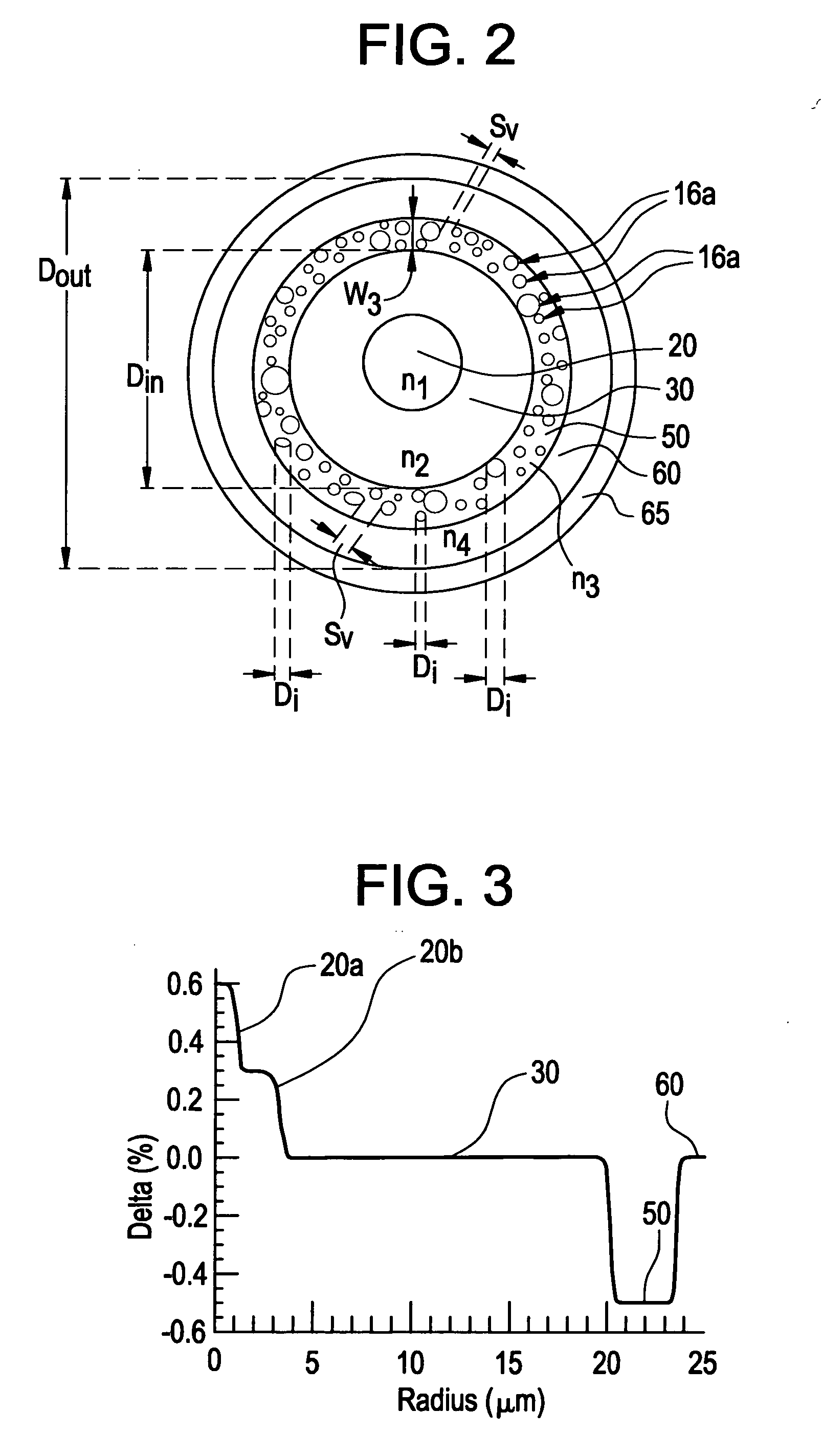
[0073]With reference to FIG. 3, in this example of fiber 10, the fiber core is divided into two parts 20A and 20B with the first segment 20A having a higher delta and the remaining core segment 20B taking an alpha shape with the alpha of about 10. This fiber has dispersions of 8.0 ps / nm / km at 1550 nm and −9.4 ps / nm / km at 1310 nm. The MFD of this fiber is 10.1 μm at 1550 nm and 8.2 μm at 1310 nm. The effective area is 75.8 μm at 1550 nm and 49.0 μm at 1310 nm. The zero dispersion wavelength is 1431 nm. Dispersion slope is 0.0657 ps / nm2 / km at 1550 nm and 0.087 ps / nm2 / km at 1310 nm. The kappa value is 124 nm at 1550 nm and −108 nm at 1310 nm. The dispersion of this fiber is 0.68 ps / nm / km at 1440 nm. The relative bending loss at 20 mm bending diameter at 1550 nm is 0.31 dB / turn.

example 10

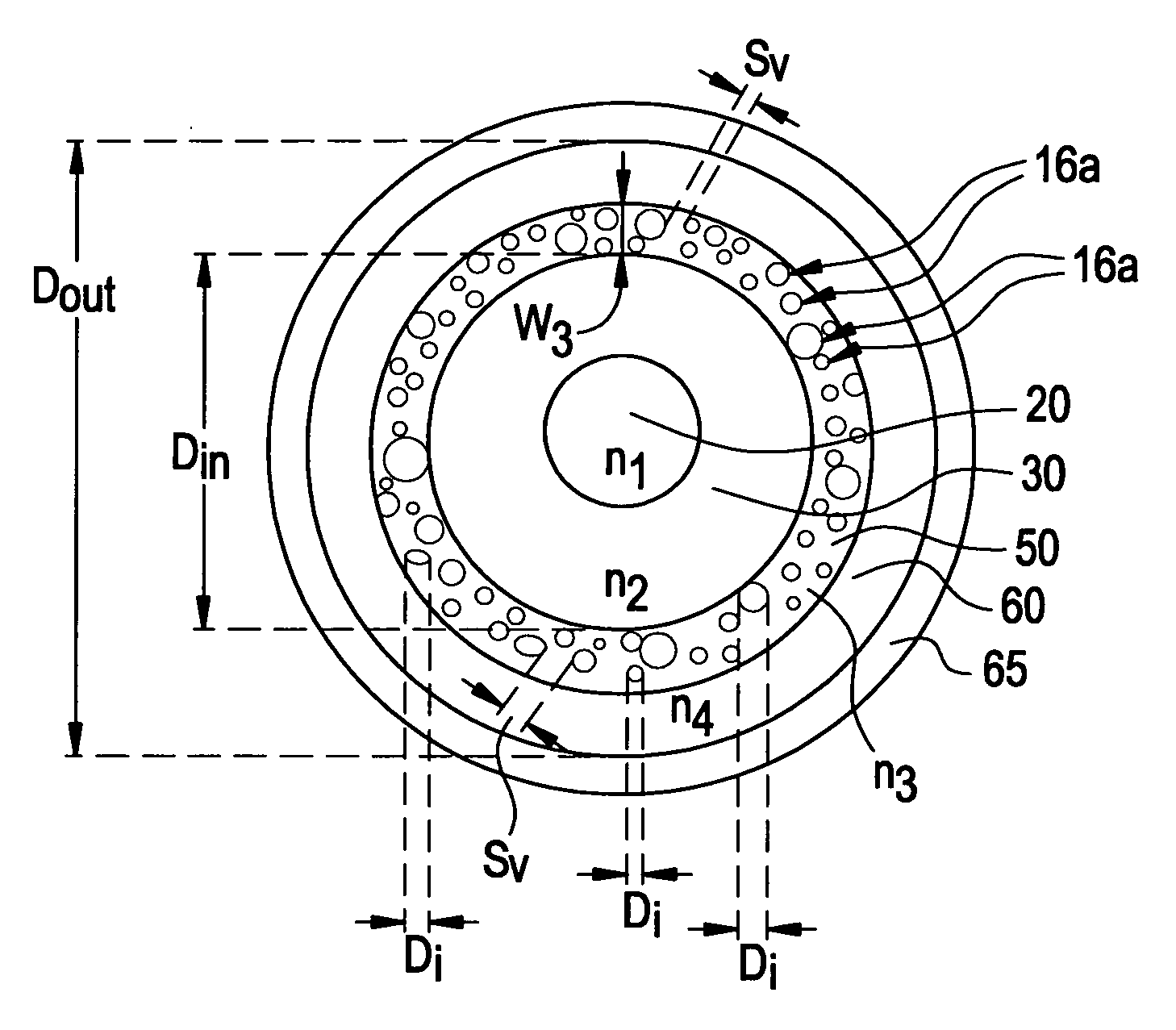
[0074]With reference to the FIG. 2 depicting airlines (voids) in the fiber region 50 (corresponding to W3), this exemplary fiber has Δ1MAX of 0.377%; R1 of 2.7 microns; V1 of 2.75 microns 2%; R2 of 14 microns; R1 / R2 of 0.19; R2MID of 8.35 microns; W2 of 11.30 microns; W3 of 2.5 microns. The voids 16A of annular region 50 contain argon. The annular region 50 begins at a radius of 14 microns radius and has a radial width of 2.5 microns. This region 50 comprises silica containing, in % of area cross-section, 6% voids (having a mean hole diameter of 300 nm with a standard deviation of 100 nm) and approximately 200 holes as view in fiber cross-section. Optical properties for this fiber are: Theoretical Cutoff wavelength of 869 nm; Zero Dispersion Wavelength of 1428 nm; MFD at 1310 nm 8.3 microns; Aeff at 1310 nm of 51.6 microns2; Dispersion at 1310 nm of −9.6 ps / nm / km; Slope at 1310 nm of 0.087 ps / nm2 / km; MFD at 1550 nm of 10.4 microns, Aeff at 1550 nm of 80.5 microns2; Dispersion at 155...

examples 11-14

[0075]With reference to the FIGS. 4A, 4B depicting airlines (voids) in the fiber region 50 (corresponding to W3), this set of exemplary fibers has a segmented core 20. More specifically, the core 20 has three annular segments: the center segment 20a characterized by maximum index delta Δ1aMAX (which is the same as Δ1MAX) and radius R1a; core segment 20b surrounding the segment 20a and characterized by Δ1bMAX and radius R1b; and a segment 20c surrounding the segment 20b and characterized by Δ1cMAX and radius R1c which is the same radius as R1. The core segment 20c is situated adjacent to and is surrounded by the fiber cladding 200.

[0076]One exemplary fiber 10 has Δ1aMAX of 0.431%; R1a of 3.6 microns; Δ1bMAX of 0.0%; R1b of 5.7 microns; Δ1cMAX of 0.125%; R1 of 8.8 microns; R2 of 15.7 microns; R1 / R2 of 0.57; R2MID of 12.4 microns; W2 of 6.8 microns; W3 of 2.1 microns. In this exemplary fiber 10 voids 16A of the annular region 50 contain argon. The annular region 50 begins at a radius o...


PUM


Abstract

An optical fiber comprising: a glass core extending from a centerline to a radius R1; a glass cladding surrounding and in contact with the core, the cladding comprising:a first annular region extending from R1 to a radius R2, the first annular region comprising a radial width, W2=R2−R1, a second annular region extending from R2 to a radius R3, the second annular region comprising a radial width, W3=R3−R2, and a third annular region extending from R3 to an outermost glass radius R4; wherein (i) the core comprises a maximum relative refractive index, Δ1MAX, relative to the third annular region; (ii) wherein the first annular region comprises a radial width W2; and (iii) the second annular region comprises a minimum relative refractive index, Δ3MIN, relative to the third annular region wherein Δ1MAX>Δ2MAX>Δ3MIN, and Δ2MIN>Δ3MIN; and the core and the cladding provide a fiber with cable cutoff less than 1500 nm, dispersion at 1550 nm less than 12 ps / nm / km, effective area at 1550 nm greater than 60 μm2, and preferably greater than 70 μm2. The second annular cladding region may contain a plurality of randomly dispersed holes.

Description

[0001]This application claims the benefit of U.S. Provisional Application No. 60 / 926,966 filed Apr. 30, 2007, entitled “Optical Fiber with Large Effective Area” and U.S. Provisional Application No. 60 / 904,133, filed Feb. 28, 2007, entitled “Optical Fiber with Large Effective Area”.BACKGROUND OF THE INVENTION[0002]1. Field of the Invention[0003]The present invention relates generally to optical fiber, and particularly to low and medium dispersion optical fibers suitable for dense wavelength division multiplexing.[0004]2. Technical Background[0005]Optical fibers such as medium dispersion fibers (MDF) with dispersion between about 6 to 12 ps / nm / km at a wavelength of 1550 nm are suitable for dense wavelength division multiplexing (DWDM). These dispersion fibers (MDFs) typically have a central core 10, with a central inner core region 11, a positive refractive index annular ring 12. The core sometimes includes at least one depressed index region 14 adjacent to the ring. The core is a fib...

Claims


Application Information

Patent Timeline
Patent Type & Authority Applications(United States)
IPC IPC(8): G02B6/02
CPCG02B6/02014G02B6/02019G02B6/02357G02B6/03688G02B6/0365G02B6/03661G02B6/02366
Inventor BICKHAM, SCOTT ROBERTSONBOOKBINDER, DANA CRAIGCHEN, XINLI, MING-JUNMISHRA, SNIGDHARAJ KUMARNOLAN, DANIEL ALOYSIUSTANDON, PUSHKAR
Owner CORNING INC
Why Eureka
Try Eureka