Injection molding machine and method for determining closure of check ring

a technology of injection molding machine and check ring, which is applied in the direction of auxillary shaping apparatus, manufacturing tools, food shaping, etc., can solve the problems of affecting the quality of molded objects, the inability to detect the time point at which the check ring closes, and the volume of injected resin to vary

Active Publication Date: 2008-12-11
FANUC LTD
View PDF7 Cites 1 Cited by
  • Summary
  • Abstract
  • Description
  • Claims
  • Application Information

AI Technical Summary

Benefits of technology

[0020]The present invention enables the time point at which the check ring closes to be detected without any additional special parts, regardless of the distance of metering stroke, by discriminating the cases in which the check ring is already closed when the screw starts moving forward, the check ring closes during the forward movement of the screw, and the check ring does not close during the forward movement of the screw.

Problems solved by technology

Since resin backflow occurs from the front to the back of the check ring after injection starts and continues until the check ring closes, variations in closure timing of the check ring cause the volume of injected resin to vary and accordingly affect the quality of molded articles.
These inventions have drawbacks, however, because they cannot detect the time point at which the check ring closes if the resin pressure does not change because the check ring is already closed when injection starts or the check ring does not close during injection.
In such a case, it is possible that the resin pressure detected by the resin pressure sensor does not match the resin pressure immediately behind the check ring, so the state of the check ring can not always be detected with accuracy.
The screw torque varies with the viscosity and pressure (injection pressure) of the resin and may cause the screw to rotate even when the check ring is closed.

Method used


Image

  • Injection molding machine and method for determining closure of check ring
  • Injection molding machine and method for determining closure of check ring
  • Injection molding machine and method for determining closure of check ring

Examples


first embodiment

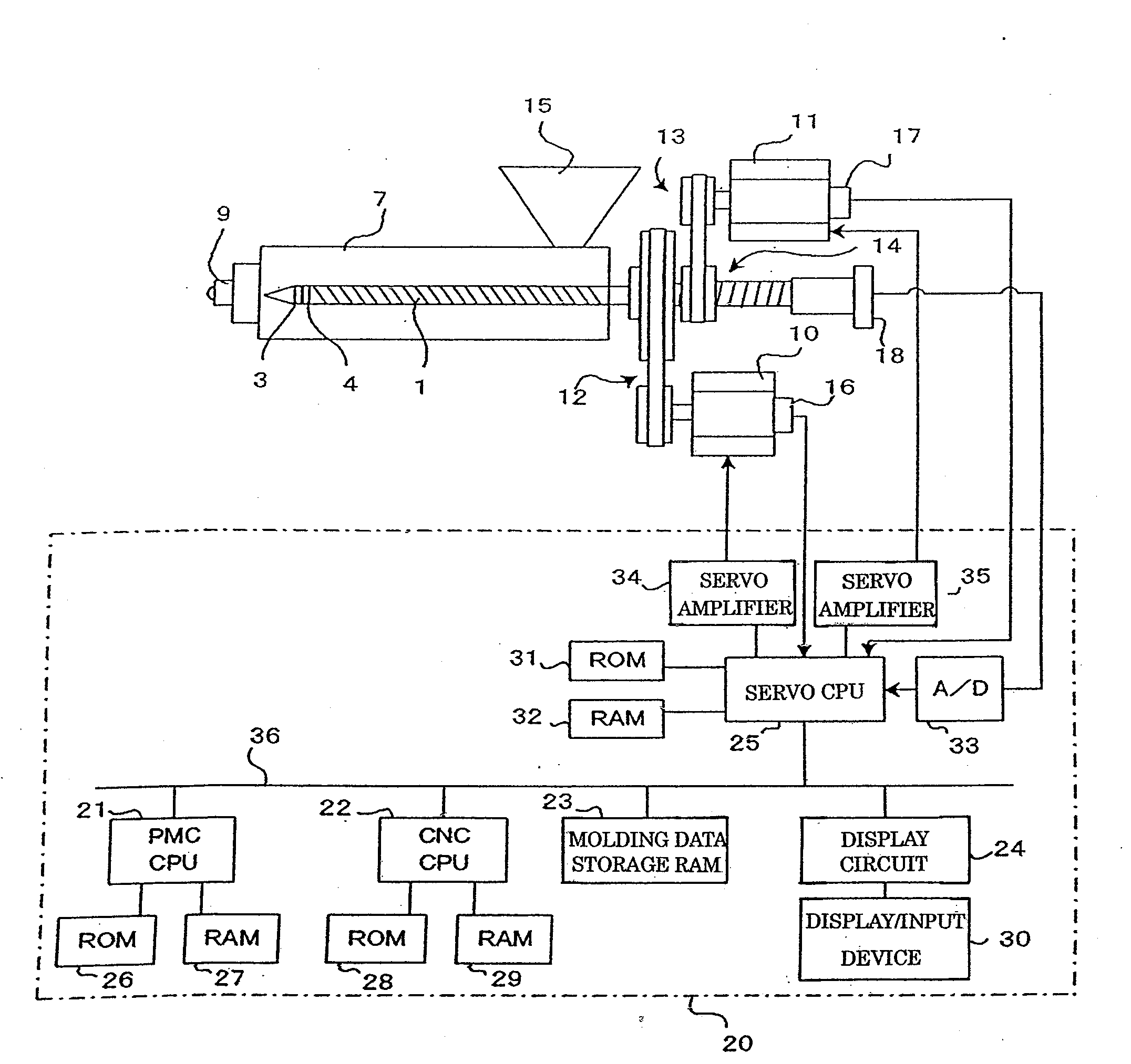
[0057]FIG. 6 is a flowchart illustrating a data collection algorithm executed by the control unit 20 at a predetermined sampling intervals in the injection / hold pressure process to collect data including resin pressures (injection pressures) P, screw torques Q, and screw positions L to detect the time point at which the check ring closes. FIG. 7 illustrates the table T provided in a memory (RAM 29) to chronologically store the data collected at each sampling cycle. FIG. 8 is a flowchart illustrating an algorithm for determining the time point at which the check ring closes by calculating coefficients of correlation on the basis of the collected data in the present invention.

[0058]When injection starts and the screw 1 moves forward, the CNC CPU 22 executes the data collecting processing shown in FIG. 6 at a predetermined sampling intervals. First, the CNC CPU 22 reads, via the servo CPU 25, the resin pressure (injection pressure) P detected by the pressure sensor 18 and input via an ...

second embodiment

[0074]FIG. 9 is a flowchart illustrating an algorithm executed to determine the time point at which the check ring closes in the present invention, in which the processing for determining the time point at which the check ring closes is omitted in each sampling cycle after the time point at which the check ring closes is determined.

[0075]The second embodiment shown in FIG. 9 is similar to the first embodiment shown in FIG. 8, except for an additional step for comparing the coefficient of correlation Ri and the reference value immediately after the coefficient of correlation Ri is calculated.

[0076]The processing in Steps c1 to c3 and Steps c5 and c6 shown in FIG. 9 is the same as the processing in Steps b1 to b5 in FIG. 8; the processing in Steps c7, c8, c10, and c11 in FIG. 9 is the same as the processing in Steps b6 to b9 in FIG. 8; and the processing in Steps c12, c13, c15, and c16 in FIG. 9 is the same as the processing in Steps b10 to b13 in FIG. 8. The processing in FIG. 9 does...

case 1

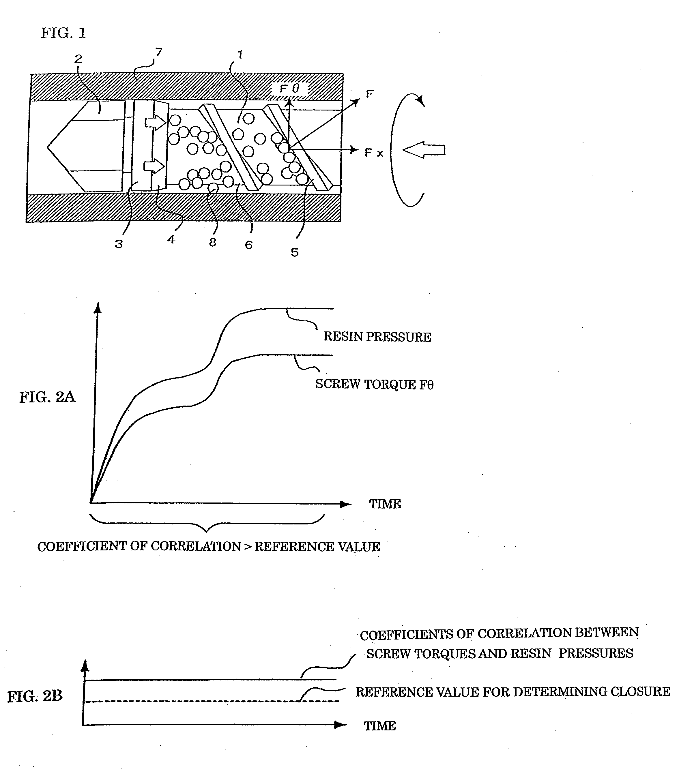
[0087] A check ring closes during the forward movement of the screw after completion of metering, and the check ring is already closed when the injection / hold pressure process starts.


PUM


Abstract

Torques and resin pressures applied to a screw are detected during the forward movement of the screw and coefficients of correlation between the detected torques and resin pressures are calculated. When the check ring is open, the flight of the screw receives resin pressure, and the screw torque increases proportionally to the resin pressure due to resin backflow, so the coefficients of correlation between the screw torques and the resin pressures are higher than a reference value. When the check ring closes, the flight of the screw no longer receive resin pressure, so the screw torque decreases and the coefficients of correlation become lower than the reference value. The check ring is determined to be closed when the coefficients of correlation become lower than the reference value.

Description

BACKGROUND OF THE INVENTION[0001]1. Field of the Invention[0002]The present invention generally relates to an injection molding machine having a check ring disposed at the front end of a screw, and more particularly to a technique for detecting the point at which the check ring closes.[0003]2. Description of the Related Art[0004]In an injection molding machine having a check ring disposed at the front end of the screw, the check ring is open when the metering of resin is completed. When injection starts with the check ring being open, the resin pressure in front of the check ring is raised as the screw moves forward, so the check ring is forced to move backward and closes the flow path of the resin. The time at which the check ring closes varies with the resin pressures in front of and behind the check ring at the time when injection starts. Since resin backflow occurs from the front to the back of the check ring after injection starts and continues until the check ring closes, vari...

Claims


Application Information

Patent Timeline
Patent Type & Authority Applications(United States)
IPC IPC(8): B29C45/76B29C45/52
CPCB29C45/52B29C45/768B29C45/77B29C2945/76006B29C2945/7602B29C2945/7618B29C2945/76187B29C2945/76381B29C2945/76575B29C2945/76698B29C2945/76859B29C2945/76996B29C2945/76658B29C2945/76929
Inventor MARUYAMA, JUNPEITAKATSUGI, SATOSHI
Owner FANUC LTD
Why Eureka
Try Eureka