
Charge stop point detecting method, charge stop point detecting device, and a battery pack

a technology of charging/discharging current and detection method, which is applied in the direction of secondary cell servicing/maintenance, instruments, safety/protection circuits, etc., can solve the problems of battery catching fire, deterioration of the life and charge/discharge capacity of the battery, and difficulty in detecting charging/discharging current, etc., to achieve accurate detection

Active Publication Date: 2015-09-01
PANASONIC ENERGY CO LTD
View PDF6 Cites 1 Cited by
  • Summary
  • Abstract
  • Description
  • Claims
  • Application Information

AI Technical Summary

Benefits of technology

This patent describes a device that can determine when to stop charging a battery. It does not rely on the battery's capacity, so it can accurately detect when it is fully charged. This allows for better control of the charging process, ensuring that the battery is always operated within safe limits. The device can be integrated into a battery pack, providing a reliable and efficient way to stop charging at the right time.

Problems solved by technology

If the battery voltage of a battery exceeds the maximum voltage, this may cause deterioration of the life and charge / discharge capacity of the battery.
Also, the battery may catch fire.
However, it is difficult to detect the charging / discharging current within the range between about ±5 mA.
In this case, the rechargeable battery may be overheated, and may accidentally catch fire or explode.
However, in the technology disclosed in JP 2002-325,363 A, when the calculated FCC or capacity is smaller than the actual capacity as discussed above, it may be determined that trouble occurs in the rechargeable battery or the charge control system even if the rechargeable battery is properly charged.

Method used


Image

  • Charge stop point detecting method, charge stop point detecting device, and a battery pack
  • Charge stop point detecting method, charge stop point detecting device, and a battery pack
  • Charge stop point detecting method, charge stop point detecting device, and a battery pack

Examples


Embodiment Construction

[0037]The following description will describe an embodiment according to the present invention with reference to the drawings.

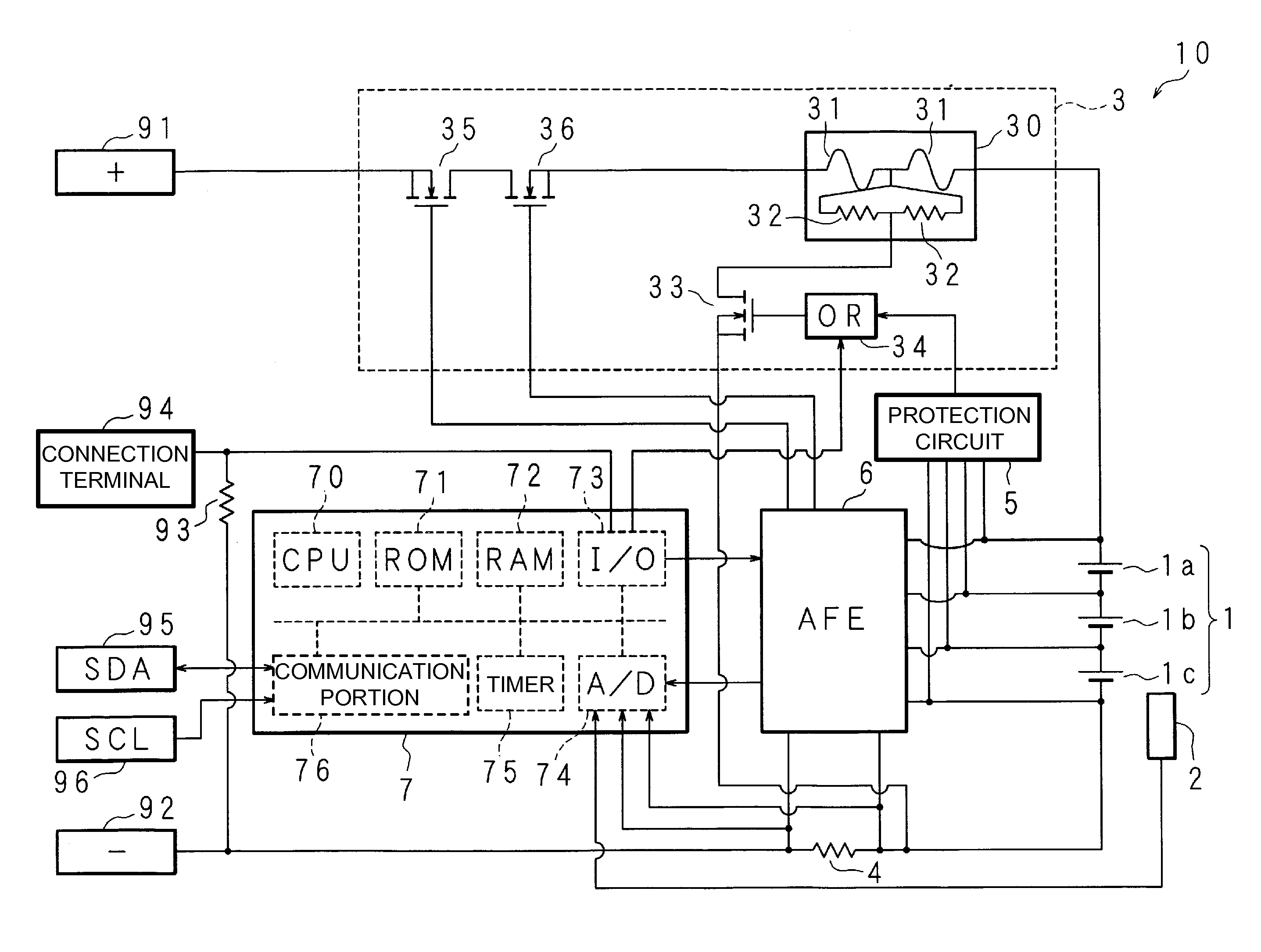
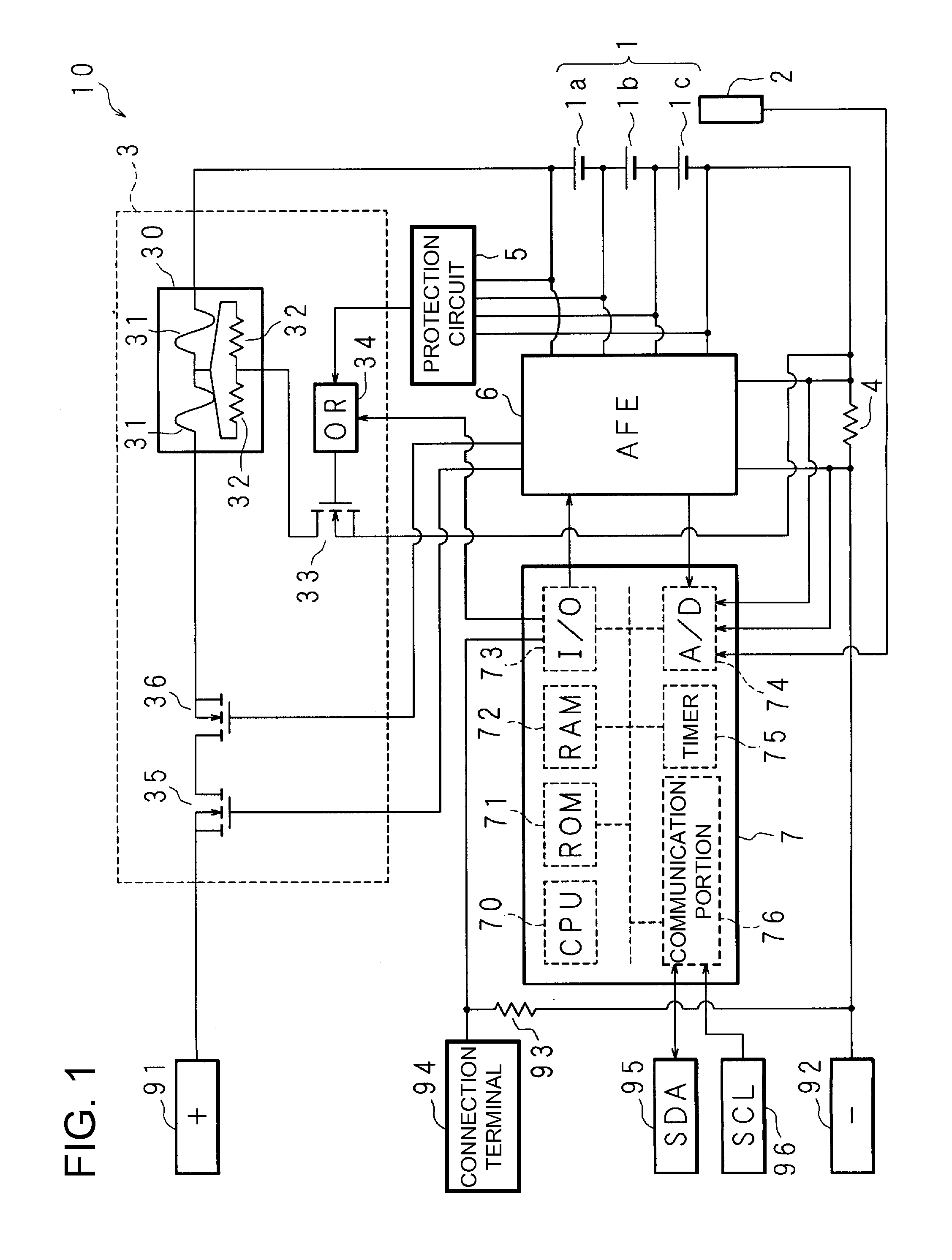
[0038]FIG. 1 is a block diagram showing the exemplary construction of a battery pack according to the present invention. As shown in this figure, a battery pack 10 includes a rechargeable battery 1, and a temperature sensor 2. The rechargeable battery 1 includes battery cells 1a, 1b, and 1c which are composed of lithium ion batteries, and are serially connected to each other in this order. The temperature sensor 2 detects the temperature of the rechargeable battery 1. The positive terminal of the battery cell 1a and the negative terminal of the battery cell 1c correspond to the positive terminal and negative terminal of the rechargeable battery 1, respectively. The rechargeable battery 1 may be other type of battery such as nickel metal hydride battery or nickel-cadmium battery. The number of the battery cells is not limited to three which compose the recharg...


PUM

PropertyMeasurementUnit
charging/discharging currentaaaaaaaaaa
voltageaaaaaaaaaa
cell voltagesaaaaaaaaaa

Abstract

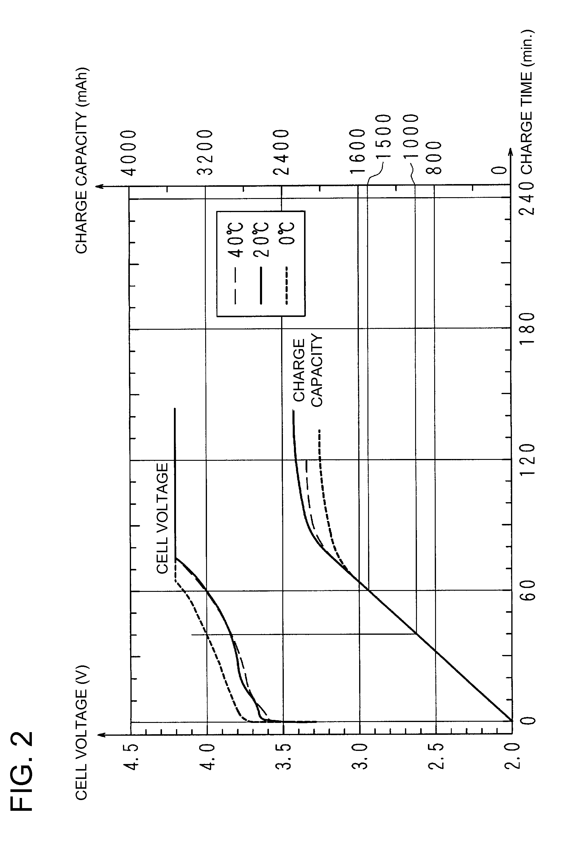
After the highest voltage of a rechargeable battery becomes higher than 4.0 V, when the charging current keeps lower than 50 mA for 20 seconds, a first point is detected for stopping charging the battery. Also, after the highest voltage becomes higher than 4.0 V, the charged capacity value and the discharged capacity value are added and subtracted for integrating the charged / discharged capacity if the highest voltage keeps higher than the integration start voltage. When the integration result shows that the battery is charged totally after the highest voltage becomes higher than 4.0 V, and when the absolute value of the integration result becomes larger than 50% of the designed capacity of the battery, the point second is detected for stopping charging the battery.

Description

BACKGROUND OF THE INVENTION[0001]1. Field of the Invention[0002]The present invention relates to a charge stop point detecting method, charge stop point detecting device, and a battery pack which detect the point for stopping charging a rechargeable battery based on capacity charged / discharged to / from the rechargeable battery.[0003]2. Description of the Related Art[0004]Conventional rechargeable batteries, typically lithium ion batteries, are charged typically by so-called constant-current / constant-voltage charging operation. In the constant-current / constant-voltage charging operation, the rechargeable batteries are first charged in a constant-current charging manner, and are then charged in a constant-voltage charging manner, in other words, the charging operation is switched from the constant-current charging manner to the constant-voltage charging manner, when the terminal voltage (hereinafter, occasionally referred to as battery voltage) reaches predetermined voltage which is pr...

Claims


Application Information

Patent Timeline
Patent Type & Authority Patents(United States)
IPC IPC(8): H02J7/00H01M10/44
CPCH01M10/44H02J7/0021H02J7/0026H02J7/0077H02J2007/0039H02J7/00304H02J7/00712Y02E60/10H02J7/0013H02J7/00308H02J7/0049
Inventor NISHIKAWA, TORUMATSUURA, SHINICHI
Owner PANASONIC ENERGY CO LTD
Learn More