Phase-tracking self-injection-locked radar

a self-injection and radar technology, applied in the direction of automatic control, measurement devices, instruments, etc., can solve the problems of difficult tracking of vital signs of moving targets, strong nonlinearity of conventional cw doppler radars for monitoring vital signs, etc., and achieve high linearity and high sensitivity

Active Publication Date: 2022-04-28
NAT SUN YAT SEN UNIV
View PDF0 Cites 0 Cited by
  • Summary
  • Abstract
  • Description
  • Claims
  • Application Information

AI Technical Summary

Benefits of technology

[0003]The phase-tracking SIL radar of the present invention uses a phase-tracking SIL loop to automatically set the relative phases between the rad...

Problems solved by technology

Therefore, the conventional CW Doppler radars for monitoring vital signs often exhibit strong nonlinearity due to the amplitude dependence on the detected position when a target mo...

Method used


Image

  • Phase-tracking self-injection-locked radar
  • Phase-tracking self-injection-locked radar
  • Phase-tracking self-injection-locked radar

Examples


first embodiment

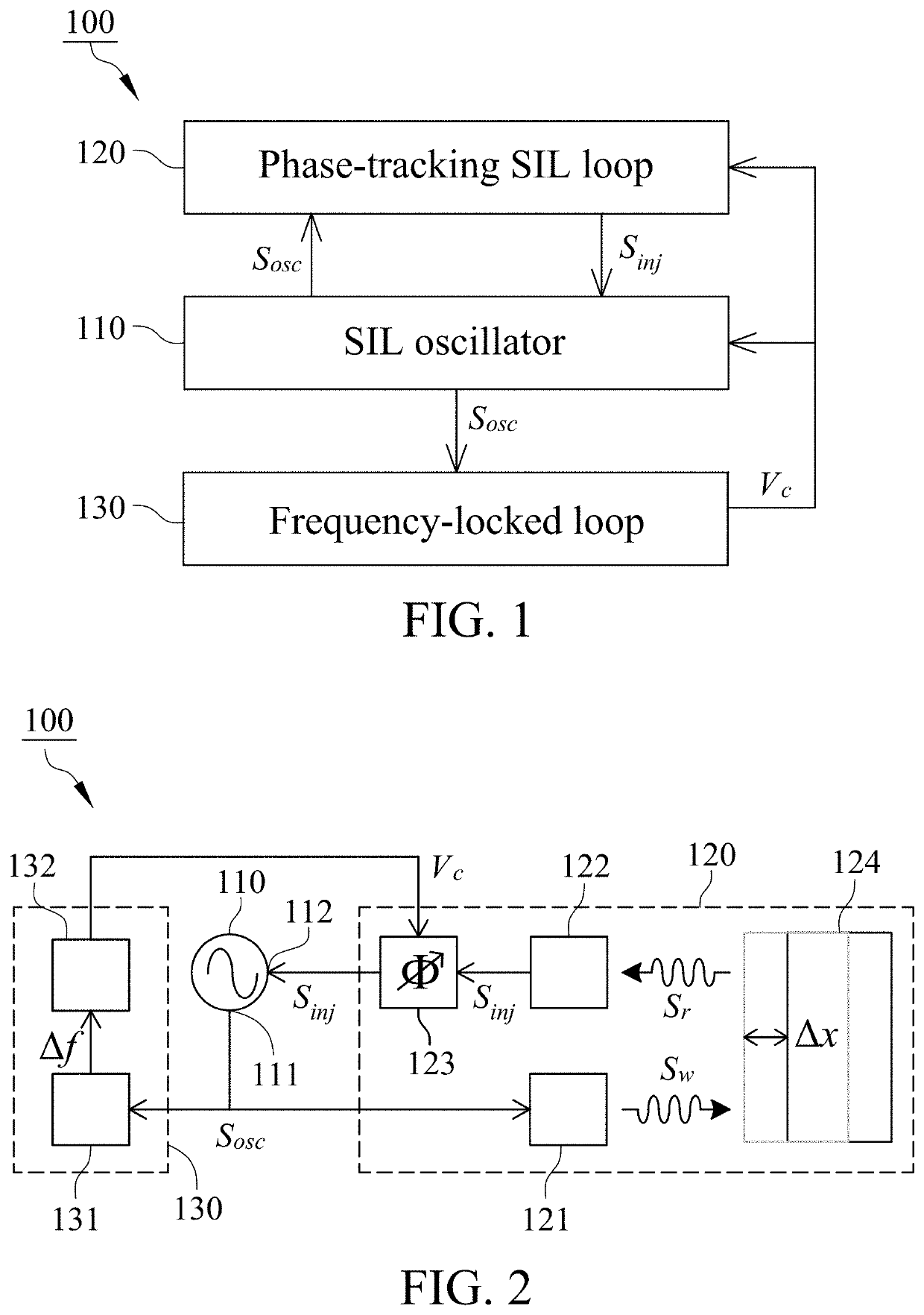
[0013]FIG. 2 is a circuit diagram of a phase-tracking SIL radar 100 in accordance with the present invention. In this embodiment, the SIL oscillator 110 has an output port 111 for delivering the electrical oscillation signal Sosc to the phase-tracking SIL loop 120 and the frequency-locked loop 130 and an injection port 112 for receiving the electrical injection signal Sinj from the phase-tracking SIL loop 120. The electrical injection signal Sinj makes the SIL oscillator 110 enter an SIL state.

[0014]The phase-tracking SIL loop 120 includes a transmitter 121, a receiver 122, a phase shifter 123 and a target 124. The transmitter 121 is electrically connected to the SIL oscillator 110 to convert the electrical oscillation signal Sosc from the SIL oscillator 110 into a wireless signal Sw for transmission to the target 124. The receiver 122 is provided to convert a reflected signal Sr from the target 124 into the electrical injection signal Sinj. The reflected signal Sr and the wireless ...

second embodiment

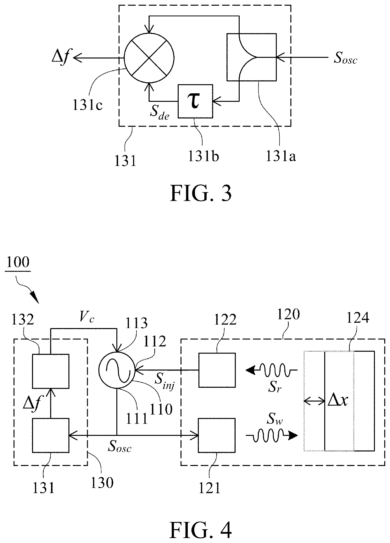
[0021]FIG. 4 is a circuit diagram of a phase-tracking SIL radar 100 of the present invention. In this embodiment, the SIL oscillator 110 further comprises a frequency control terminal 113. The phase-tracking SIL loop 120 includes the transmitter 121, the receiver 122 and the target 124, and excludes the phase shifter 123. The transmitter 121 is electrically connected to the SIL oscillator 110 to convert the electrical oscillation signal Sosc from the SIL oscillator 110 into the wireless signal Sw for transmission to the target 124. The receiver 122 converts the reflected signal Sr from the target 124 into the electrical injection signal Sinj for injection into the SIL oscillator 110.

[0022]With reference to FIG. 4, the frequency-locked loop 130 includes the frequency demodulator 131 and the controller 132. The frequency demodulator 131 is electrically connected to the SIL oscillator 110 to demodulate the electrical oscillation signal Sosc from the SIL oscillator 110 into the electric...


PUM


Abstract

A phase-tracking self-injection-locked (SIL) radar includes an SIL oscillator, a phase-tracking SIL loop and a frequency-locked loop. The SIL oscillator generates an electrical oscillation signal and receives an electrical injection signal related to the electrical oscillation signal for self-injection locking. The phase-tracking SIL loop receives the electrical oscillation signal and outputs the electrical injection signal to the SIL oscillator with a constant phase difference between the electrical oscillation signal and the electrical injection signal. The frequency-locked loop receives the electrical oscillation signal and produces an electrical control signal to control the phase-tracking SIL loop or the SIL oscillator for eliminating the frequency shift of the SIL oscillator caused by the phase-tracking SIL loop. Accordingly, the phase difference between the electrical oscillation signal and the electrical injection signal is maintained at 0° or 180° such that the phase-tracking SIL radar operates at optimal detection points.

Description

FIELD OF THE INVENTION[0001]This invention generally relates to a self-injection-locked (SIL) radar, and more particularly to a phase-tracking SIL radar.BACKGROUND OF THE INVENTION[0002]Continuous-wave (CW) Doppler radars are widely used to monitor vital signs of people or animals. In recent years, SIL radar, one of the conventional CW Doppler radars, has received increasing attention because of its extraordinarily high sensitivity of vital sign detection. However, the conventional CW Doppler radars including the SIL radar for detecting vital signs are known to have optimal and null detection points. The optimal and null detection points occur alternatively every eighth wavelength where the maximum and minimum amplitudes of the detected vital signs are at the optimal and null detection points, respectively. Therefore, the conventional CW Doppler radars for monitoring vital signs often exhibit strong nonlinearity due to the amplitude dependence on the detected position when a target ...

Claims


Application Information

Patent Timeline
IPC IPC(8): G01S7/35H03L7/08
CPCG01S7/352G01S13/50H03L7/08H03L7/099G01S13/88G01S7/02G01S13/58H03L7/24
Inventor HORNG, TZYY-SHENGYU, SHIANG-HWUAPENG, KANG-CHUNSU, WEI-CHIH
Owner NAT SUN YAT SEN UNIV
Why Eureka
Try Eureka