Endoscopic treatment tool

a technology for endoscopic treatment and tools, applied in the field of endoscopic treatment tools, can solve the problems of insufficient incision and excision, and achieve the effect of increasing rigidity

Active Publication Date: 2008-12-11
OLYMPUS CORP
View PDF22 Cites 30 Cited by
  • Summary
  • Abstract
  • Description
  • Claims
  • Application Information

AI Technical Summary

Benefits of technology

[0011]An endoscopic treatment tool according to the present invention includes a flexible sheath; an operating member inserted to the sheath so as to freely advance and retract; a treatment section disposed at the distal end of the operating member that protrudes and retracts from the sheath; and an operator section connected to the proximal end of the operating member including a sliding member which makes the operating member advance and retract. The endoscopic treatment tool according to the present invention includes the operating member consisting of a member which increases the rigidity by compression and a member which compresses the operating member.
[0012]By providing the structure above, when the treatment section is made to protrude from the distal end of the sheath to perform an operation such as incision or excision by moving around the target site, a deflection can be prevented by increasing the rigidity of the sheath by compressing the operating member. Therefore a sufficient incision or excision and so on can be achieved relative to the distance of movement of the treatment tool.

Problems solved by technology

At this time, backward deflection to the direction of movement of a sheath 103 occurs after the treatment tool is moved due to the flexibility of the sheath 103 of the high-frequency treatment tool 101, hence there have often been problems of insufficient incision and excision relative to the distance of movement of the treatment tool.
Even the treatment tools provided with a tightly wound coil as the flexible tube or the operating wire such as those disclosed in Japanese Patent Application, First Publication No. 8-299355 and Japanese Patent Application, First Publication No. 2005-230080 have the same problems due to the flexibility of the tightly wound coil.

Method used


Image

  • Endoscopic treatment tool
  • Endoscopic treatment tool
  • Endoscopic treatment tool

Examples


first embodiment

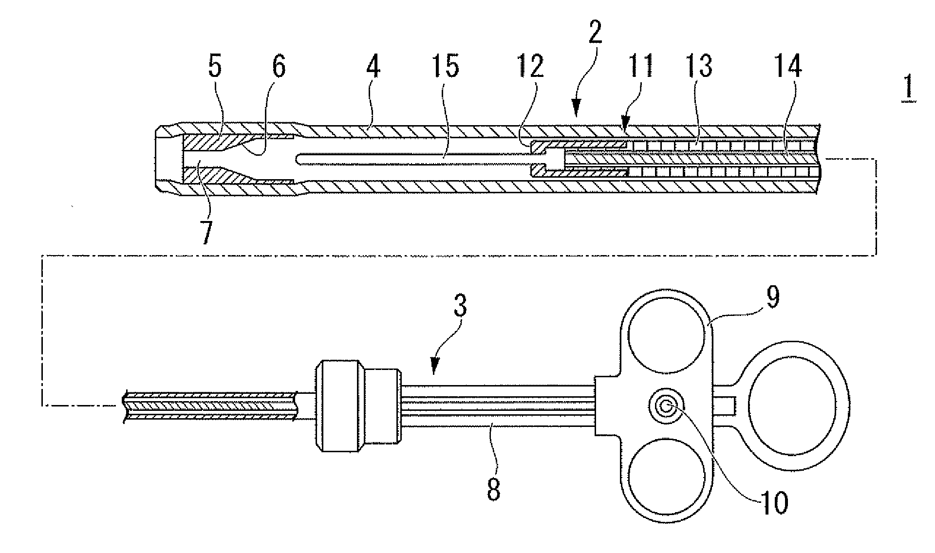
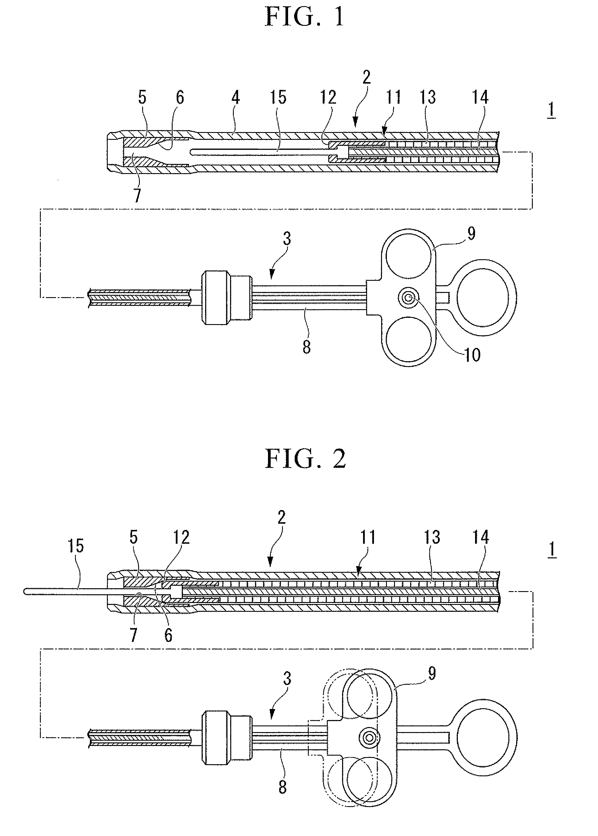
[0034]A first embodiment of the present invention will be explained with reference to FIGS. 1 and 2.

[0035]As shown in FIG. 1, a high-frequency knife (endoscopic treatment tool) 1 according to the present embodiment includes a flexible sheath 2 which can be inserted to an endoscopic channel (not shown) as a main body, and an operator section 3 disposed at the proximal end of the sheath 2. The sheath 2 includes an insulating tube 4, for instance made of tetrafluoroethylene and so on.

[0036]A pipe-like stopper member (abutting member) 5 is disposed at the distal end of the sheath 2 and an outer periphery of the stopper 5 is covered with the distal portion of the insulating tube 4. The inner surface of the stopper 5 has a tapered portion 6 with a reduced diameter toward the distal side, and a small diameter hole 7 is formed at the distal side of the tapered portion 6.

[0037]The operator section 3 of the high-frequency knife 1 includes an operator main body 8 and an operating slider 9 whic...

second embodiment

[0048]FIGS. 5 and 6 show a second embodiment of the present invention.

[0049]In the high-frequency knife 1 of the present embodiment, the operator section 3 is provided with a holding member 19 which prevents retraction of the operating slider 9 and holds the electrode knife 15 at a protruded position. The holding member 19 includes an external thread 20 disposed on the operator main body 8 at the rear end of the operating slider 9 and a mobile member 21 engages therewith. The second embodiment differs from the first embodiment at this point.

[0050]Furthermore, the operation of the present embodiment differs from the first embodiment by means of operating the holding member 19. That is, the mobile member 21 is advanced by rotating the mobile member 21 relative to the external thread 20 from the position where the electrode knife 15 is protruded from the distal end of the sheath 2 (refer to FIG. 5).

[0051]The operating member 11 is then compressed and the operating slider 9 is made to a...

third embodiment

[0053]FIGS. 7 to 9 show a third embodiment of the present invention.

[0054]In the high-frequency knife 1 of the present embodiment, the operator section 3 is provided with a ratchet device 23 which prevents the operating slider 9 from retracting and holds the electrode knife 15 at the protruded position as by means a holding member 22. The ratchet device 23 includes a plurality of slanting teeth 24 disposed on the distal side of the operator main body 8 with respect to the operating slider 9, and a pawl 27 which is pivotally mounted at the distal end of the operating slider 9 by a pin 25 and is spring-biased by a spring 26 toward the direction of clutching with the slanting teeth 24. The third embodiment differs from the first embodiment at this point.

[0055]Furthermore, the operation of the third embodiment differs from the first embodiment by means of operating the ratchet device 23. In particular, when the operating slider 9 is advanced, the pawl 27 of the ratchet device 23 crosses...


PUM


Abstract

An endoscopic treatment tool includes a flexible sheath; an operating member inserted to the sheath so as to freely advance and retract; a treatment section disposed at the distal end of the operating member that protrudes and retracts from the sheath; and an operator section connected to the proximal end of the operating member including a sliding member which makes the operating member advance and retract. The endoscopic treatment tool includes the operating member consisting of a member which increases its rigidity by compression, and a member which compresses the operating member. Therefore a sufficient incision or excision is achieved relative to the distance of movement of the treatment tool by preventing a deflection of the flexible tube when in use.

Description

BACKGROUND OF THE INVENTION[0001]1. Field of the Invention[0002]The present invention relates to endoscopic treatment tools, in particular to treatment tools such as a high-frequency knife for incising biological tissue.[0003]2. Description of the Related Art[0004]Conventionally, a treatment procedure for incising biological tissue such as a mucous membrane has been conducted endoscopically. In such an incision procedure, a high-frequency treatment tool disclosed in such as Japanese Unexamined Utility Model Application, Publication No. S62-50610 is used.[0005]The high-frequency treatment tool such as disclosed in the above document and Japanese Patent Application, First Publication No. Hei 8-299355, and Japanese Patent Application, First Publication No. 2005-230080, include a needle-like electrode (treatment section) which extends to an axial direction disposed at a distal end of an operating wire inserted through a flexible sheath. Biological tissue which is in contact with the ele...

Claims


Application Information

Patent Timeline
Patent Type & Authority Applications(United States)
IPC IPC(8): A61B1/00A61B17/32
CPCA61B18/1492A61B2017/00336A61B2017/0034A61B2018/1475
Inventor OKADA, TSUTOMU
Owner OLYMPUS CORP
Why Eureka
Try Eureka