

Brain wave detecting apparatus
- Summary
- Abstract
- Description
- Claims
- Application Information
AI Technical Summary
Benefits of technology
Problems solved by technology
Method used
Image

Examples
Embodiment Construction
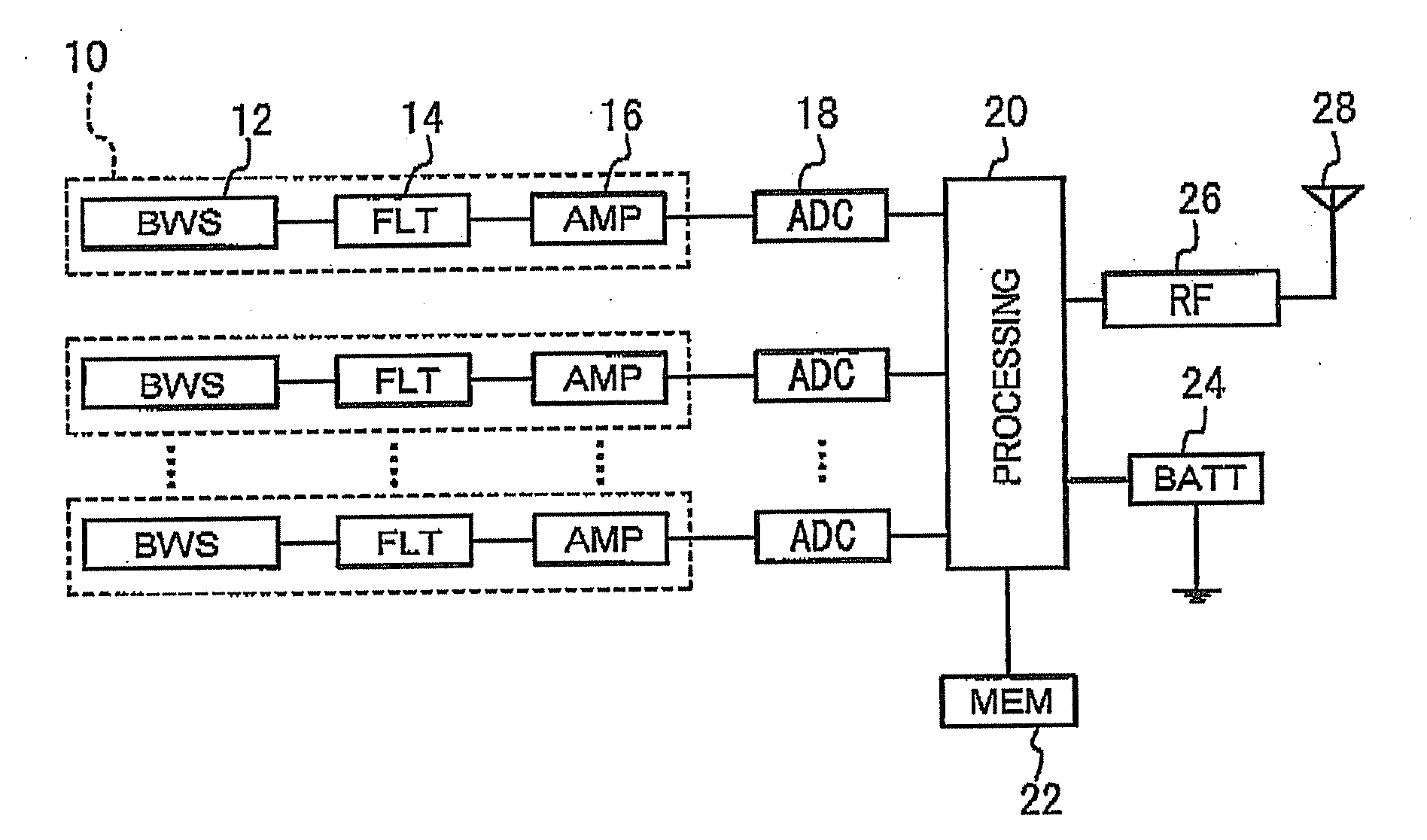
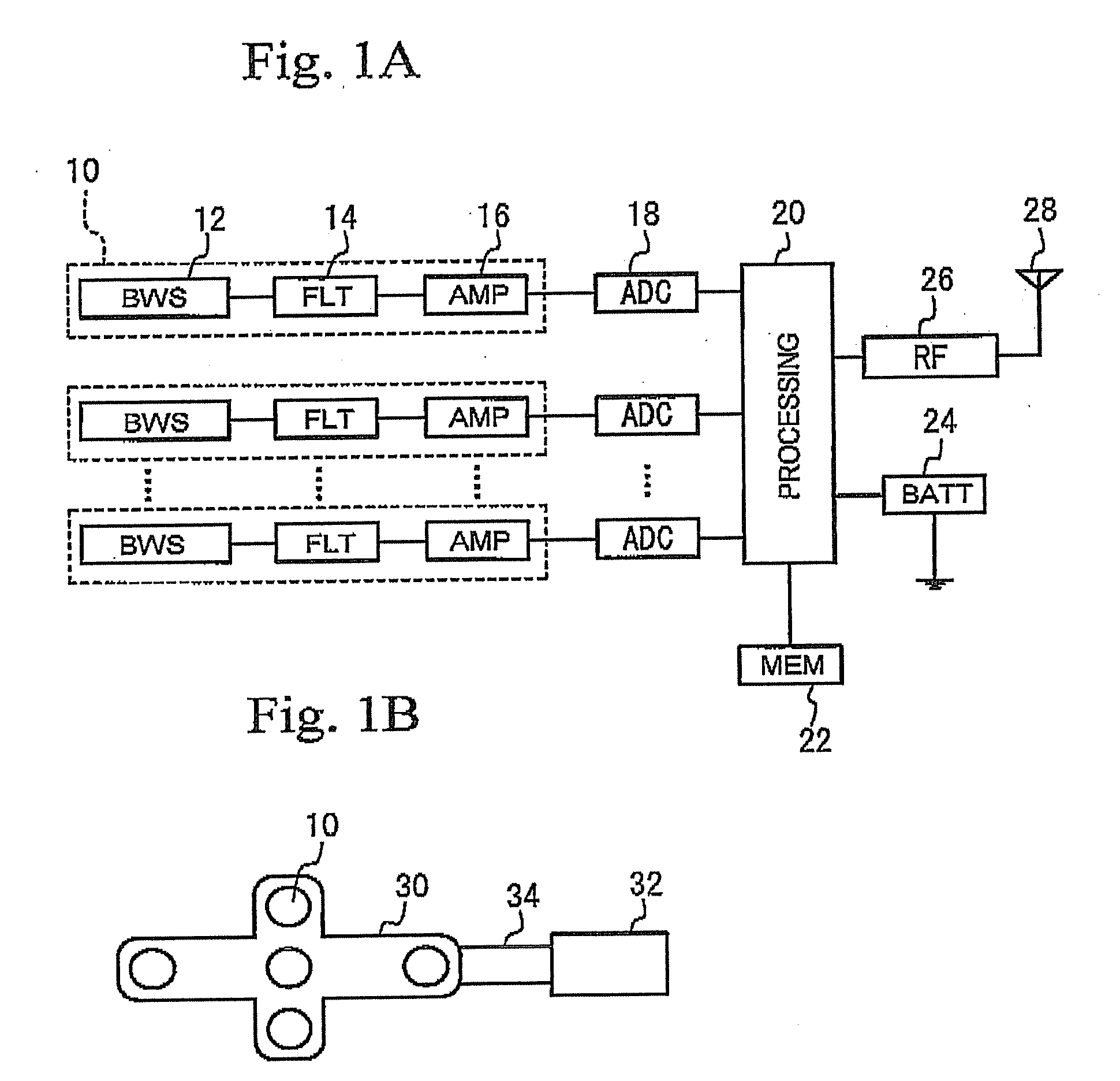
[0014]FIG. 1A is a block diagram of a brain wave detecting apparatus in accordance with a first embodiment. The bran wave detecting apparatus has a plurality of brain wave detecting portions 10, each being composed of a brain wave sensor (BWS) 12, a filter (FLT) 14, and an amplifier (AMP) 16. Further, the brain wave detecting apparatus includes multiple analog-to-digital converters (ADC) 18, a processing portion 20, a memory (MEM) 22, a battery (BATT) 24, a radio frequency (RF) circuit 26, and an antenna 28. The brain wave detecting portions 10 are coupled with the processing portion 20 via the respective ADCs 18. In each of the brain wave detecting portions 10, the brain wave sensor 12 is arranged on a head of a user such as a driver. The filter 14 eliminates noise of unnecessary frequencies from the analog brain wave signal detected by the brain wave sensor 12. The analog brain wave signal thus filtered is amplified by the amplifier 16 and is then converted to a digital brain wave...
PUM
 Abstract
Description
Claims
Application Information