
Fixation suture device and method

Inactive Publication Date: 2008-12-11
STCHUR ROBERT P
View PDF26 Cites 59 Cited by
  • Summary
  • Abstract
  • Description
  • Claims
  • Application Information

AI Technical Summary

Benefits of technology

[0008]The primary object of the present invention is to provide a fixation suture device and method that reduces the amount of time to perform a rotator cuff repair and to provide a more secure fixation of a rotator cuff tendon.
[0009]A further object of the present invention is to provide a fixation suture device and method that eliminates the need for tying suture knots.

Problems solved by technology

However, the act of tying knots and overall suture management is very time-consuming.
In addition, the greater the number of sutures used, the more confusion is created when ultimately tying the suture knots.
However, the current devices are complicated, unreliable and, like all current techniques, often require multiple implants.
In addition, the tension applied to the rotator cuff tendon is often uneven in distribution.
Therefore, due to these inefficiencies related to the suturing and fixation of the rotator cuff tendon, surgeons spend unneeded time and energy on this procedure and, more importantly, patients are exposed to an unnecessary amount of time under anesthesia.

Method used


Image

  • Fixation suture device and method
  • Fixation suture device and method
  • Fixation suture device and method

Examples


fifth embodiment

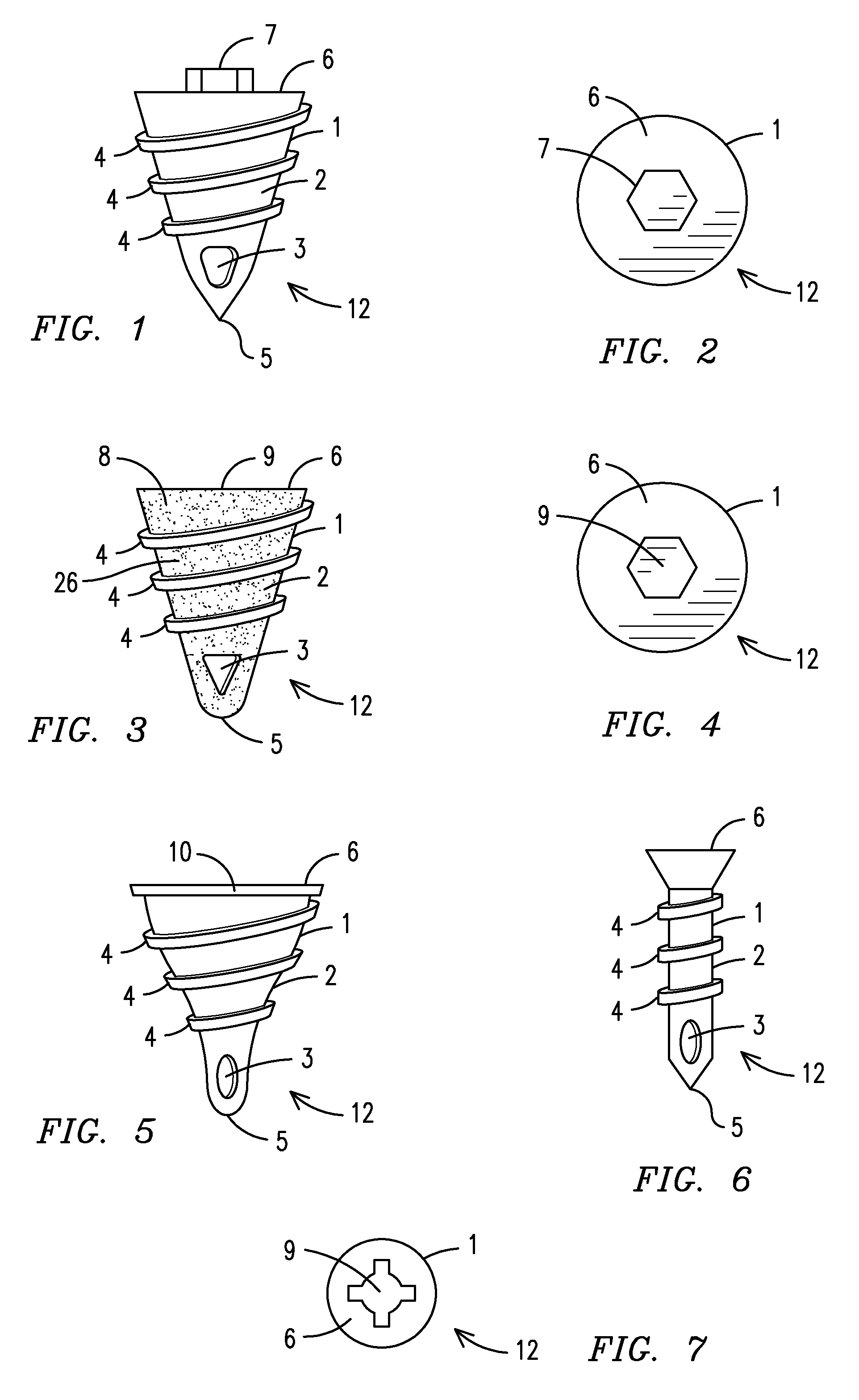
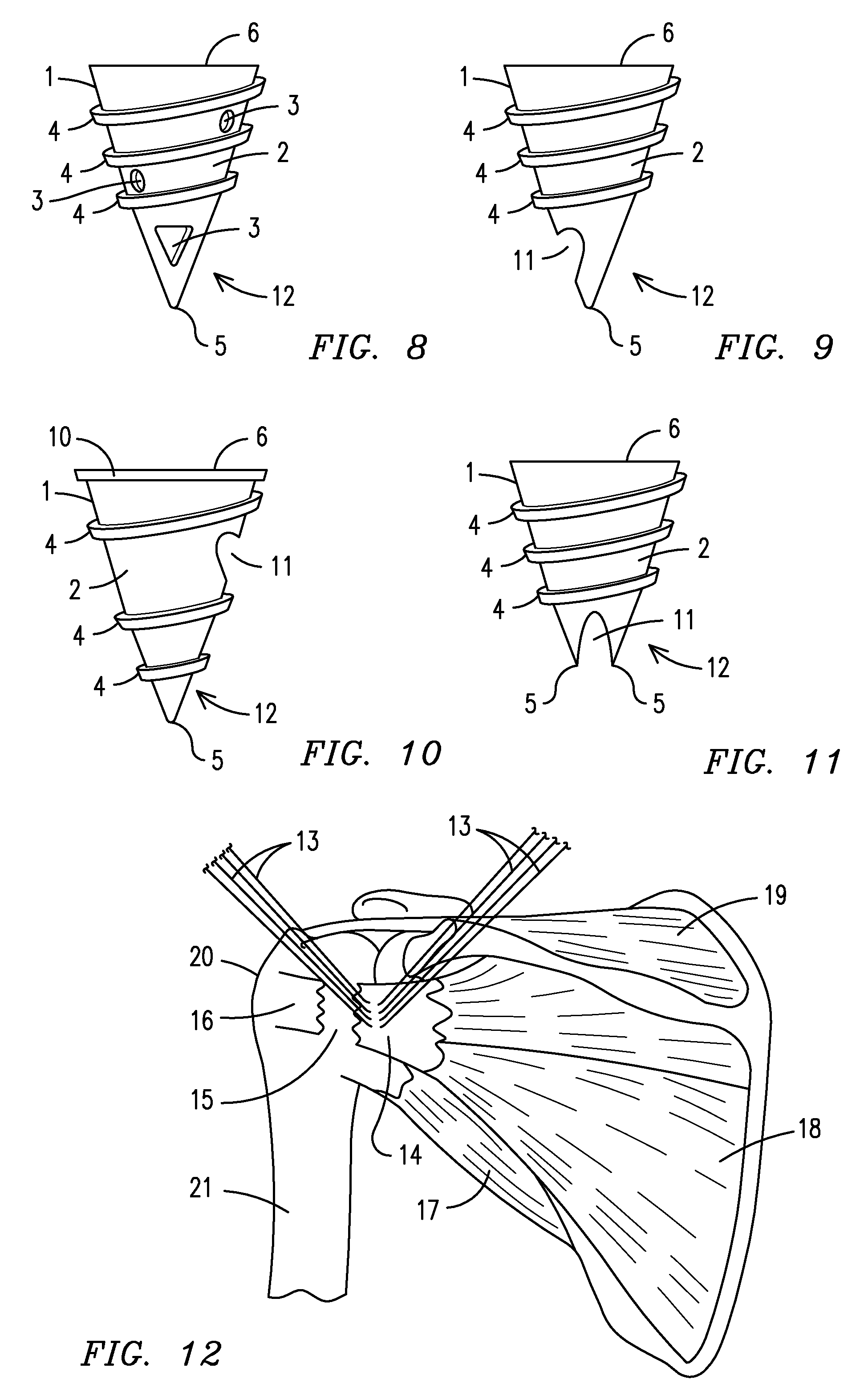
[0053]With reference to FIG. 8, a side perspective view of the fixation suture device of the present invention is shown. Rather than having one anchor aperture 3 located on the anchor tip 5, a plurality of anchor apertures 3 are located on the anchor core 2, as well as on the anchor tip 5.

eighth embodiment

[0054]FIGS. 9-10 show perspective views a sixth, seventh and eighth embodiment of the fixation suture device of the present invention. Rather than having at least one anchor aperture 3, these embodiments of the fixation suture device 12 include at least one notch 11 located at various places on the anchor 1, including adjacent to the tip 5 (see FIG. 9), on the anchor core 2 (see FIG. 10) and on the anchor tip 5 (see FIG. 10). Similar to the aforementioned embodiments wherein at least one suture 13 is threaded through the apertures 3, at least one suture 13 is threaded through the notch 11 in these embodiments (not shown).

[0055]Next, FIG. 12 shows a posterior plan view of a plurality of sutures being passed through a rotator cuff tendon. The muscles located on the back of a person include the supia spinatus 19, the infra spinatus 18 and the teres minor 17 wherein a rotator cuff tendon 14 is attached to the humeral head 20 of a humerus 21 (not shown). A rotator cuff tear 15 commonly o...


PUM


Abstract

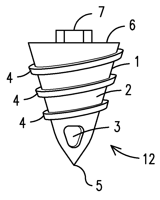
A fixation suture device (12) wherein an anchor (1) has a top (6), a core (2) and a tip (5) and external threads (4) located on the anchor core (2). An anchor aperture (3) is located on the anchor (1) for acceptance of sutures (13). To use the device (12), a surgeon passes the sutures (13) through a rotator cuff tendon (14). Then, the sutures (13) are passed through the anchor aperture (3) and the anchor tip (5) is positioned against a humerus (21) via a handle (22) and cannula (23). The surgeon pushes downward on the handle (22) to provide a downward force on the anchor (1) while pulling upward on the sutures (13) in order to produce a desired tension on the rotator cuff tendon (14). The surgeon rotates the anchor (1) into the humerus (21) while maintaining tension on the sutures (13). As the anchor (1) is rotated deeper and deeper into the humerus (21), the sutures (13) secured to the rotator cuff tendon (14) wind around the anchor core (2), thereby pulling the rotator cuff tendon (14) closer and closer to the anchor (1). When the anchor top (6) is in alignment with or located below the humerus (21), the sutures (13) wrap around the sutures (13) held by the surgeon to create a wrap (24).

Description

BACKGROUND OF THE INVENTION[0001]This invention relates to suture devices, more particularly, a fixation suture device that permits a user to quickly and easily fixate a suture without the need to tie conventional suture knots.[0002]As with any medical procedure wherein a patient undergoes surgery, there is always concern relating to the amount of time the wound is exposed and the length of time spent under anesthesia. Thus, time is of the essence when operating on a patient.[0003]Currently, arthroscopic rotator cuff operations are commonly performed for rotator cuff tears wherein a central point on the greater tuberosity is commonly found to be the symmetrical origin of the tear. The rotator cuff tear is repaired by using a plurality of sutures which are inserted through the rotator cuff tendon, usually on the greater tuberosity, wherein the sutures are ultimately knotted to maintain tension on the rotator cuff tendon, thereby permitting a person to have function of the rotator cuf...

Claims


Application Information

Patent Timeline
IPC IPC(8): A61L17/00A61B17/04A61B17/58
CPCA61B17/0401A61B2017/0409A61B2017/0414A61B2017/044
Inventor STCHUR, ROBERT P.
Owner STCHUR ROBERT P
Learn More