Scissors with a blade having a tapered center for hinge

a technology of scissors and hinges, which is applied in the field of scissors equipped with blades, can solve the problems of reducing friction force but not desirable for human hair cutting, and achieve the effects of reducing friction force, reducing friction force, and maximum friction force between the two blades

Inactive Publication Date: 2008-12-18
JUN DONG HO
View PDF6 Cites 7 Cited by
  • Summary
  • Abstract
  • Description
  • Claims
  • Application Information

AI Technical Summary

Benefits of technology

[0005]Almost all of scissors developed up to now have blades that cross over each other without angle. Two blades of scissors overlap each other without any space between them from the first moment when the scissors is open to the last moment when the scissors is closed. Therefore, friction force between the two blades is maximum. It burdens a barber's finger to overcome the friction between the blades. If some gap is formed intently to reduce the friction force between the blades, hairs of a customer are inserted between the gaps. Then the hairs are not cut clearly or are not cut at all. Adding some lubricant to the blades may reduce the friction force but not desirable for human hair cut. It is a purpose of the current application to provide a human hair cutting scissors that causes less friction force between two blades than previous scissors by introducing one blade, which a central part that is tapered along the narrow axis of the blade and a hinge hole is developed thereon. The scissors according to current application enables a more clear cut of a human hair than scissors of prior art. The scissors according to current application has a specially designed first blade. The specially designed first blade has a central part, on which a hinge hole is developed. The central part is tapered along the narrow axis of the blade. The tapered central part of the first blade allows the second blade of the scissors to cross over the first blade with a predetermined angle. Therefore, the second blade's wide edge crosses over the first blade's wide edge with a pre-determined angle and sweeps wide surface of the first blade with an angle. Such angled cross over of the blades provides a more precise cut of customer's hair as a barber intended.

Problems solved by technology

Adding some lubricant to the blades may reduce the friction force but not desirable for human hair cut.

Method used


Image

  • Scissors with a blade having a tapered center for hinge
  • Scissors with a blade having a tapered center for hinge
  • Scissors with a blade having a tapered center for hinge

Examples


first embodiment

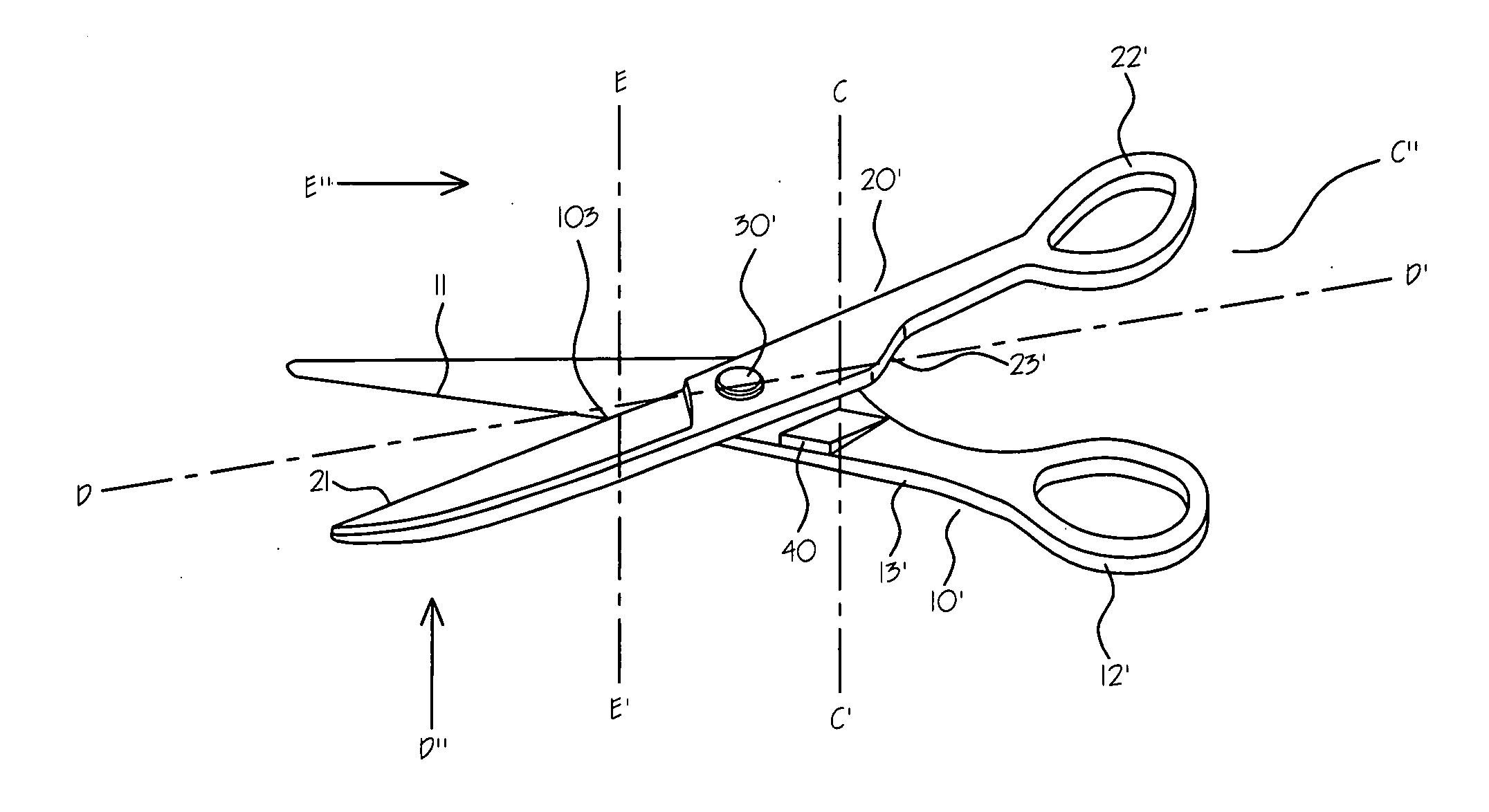
[0027]FIG. 3 is a perspective view of first embodiment of a scissors (2) according to current application. The scissors (2) according to current application is comprised of a first member (10′) and a second member (20′) pivotally connected by a fastening member (30′). The first member (10′) is comprised of a first blade portion (11′), a first handle portion (13′) and a first ringlet (12′). The second member (20′) is comprised of a second blade portion (21′), a second handle portion (23′) and a second ringlet (22′). A small tapered hump (40) is developed on the surface of the first handle portion (13′), which faces the second handle portion (23′).

[0028]FIG. 4-a is a cross-sectional view of the first embodiment of the scissors (2) according to current application seen along line C-C′ in FIG. 3 when the scissors (2) is fully open seen from the view point C″. When the scissors (2) is fully open, the two members (10′) and (20′) contact horizontally. FIG. 4-b is a side view of the first e...

fourth embodiment

[0037]FIG. 9-b is a cross-sectional view of fourth embodiment of the scissors according to current application seen along line E-E′ in FIG. 3 as the scissors changes position from fully open state to totally closed state, seen from the view point E″. In this case, the angle (104) between the two blades changes from negative to positive as the scissors (2) changes from open state to closed state.

[0038]FIG. 10 is a cross-sectional view of fifth embodiment of the scissors (2) according to current application seen along line C-C′ in FIG. 3 when the scissors is totally closed, seen from the view point C″. In the fifth embodiment, the handle portions (13′) and (23′) of both of the members (10′) and (20′) are convexly carved. In this case, the angle (104) between the two blades also changes from negative to positive as the scissors (2) changes from open state to closed state, as shown in FIG. 9-b.

[0039]FIG. 11 is a cross-sectional view of sixth embodiment of the scissors (2) according to ...

seventh embodiment

[0040]FIG. 12 is a cross-sectional view of seventh embodiment of the scissors according to current application seen along line C-C′ in FIG. 3 when the scissors is totally closed, seen from the view point C″. In the seven embodiment, the handle portions (13′) and (23′) of both of the members (10′) and (20′) are trapezoidally carved. In this case, the angle (104) between the two blades also changes from negative to positive as the scissors (2) changes from open state to closed state, as shown in FIG. 9-b.

[0041]As described above, it is obvious that a person of ordinary skill in the field of this area can easily modify the structure of the handle portion of a scissors according to teaching of the current application.


PUM


Abstract

A scissors is provided. The scissors according to current application has a specially designed first blade. The specially designed first blade has a tapered bump at the central part, on which a hinge hole is developed. The tapered bump on the first blade allow the second blade of the scissors to cross over the first blade with an angle. Therefore, the second blade's wide edge crosses over the first blade's wide edge with an angle and sweeps wide surface of the first blade with an angle. Such angled cross over of the blades provides a more precise cut of customer's hair as a barber intended.

Description

FIELD OF THE INVENTION[0001]Current application relates to a scissors, especially to a scissors equipped with a blade that has a tapered center for hinge to provide a more precise hair cut as a barber intends.BACKGROUND OF THE INVENTION[0002]Almost all of scissors developed up to now have blades that cross over each other without angle. Two blades of scissors overlap each other without any space between them from the first moment when the scissors is open to the last moment when the scissors is closed. Therefore, friction force between the two blades is maximum. It burdens a barber's finger to overcome the friction between the blades. If some gap is formed intently to reduce the friction force between the blades, hairs of a customer are inserted between the gaps. Then the hairs are not cut clearly or are not cut at all. Adding some lubricant to the blades may reduce the friction force but not desirable for human hair cut. It is a purpose of the current application to provide a human...

Claims


Application Information

Patent Timeline
Patent Type & Authority Applications(United States)
IPC IPC(8): B26B13/00
CPCB26B13/24B26B13/285
Inventor JUN, DONG HO
Owner JUN DONG HO
Why Eureka
Try Eureka