Cooling system and method utilizing thermal capacitor unit(s) for enhanced thermal energy transfer efficiency

a cooling system and capacitor technology, applied in the field of cooling systems and methods, can solve the problems of low efficiency of the cooling system, achieve the effects of facilitating efficient thermal energy transfer, and facilitating thermal energy extraction

Inactive Publication Date: 2008-12-18
IBM CORP
View PDF10 Cites 75 Cited by
  • Summary
  • Abstract
  • Description
  • Claims
  • Application Information

AI Technical Summary

Benefits of technology

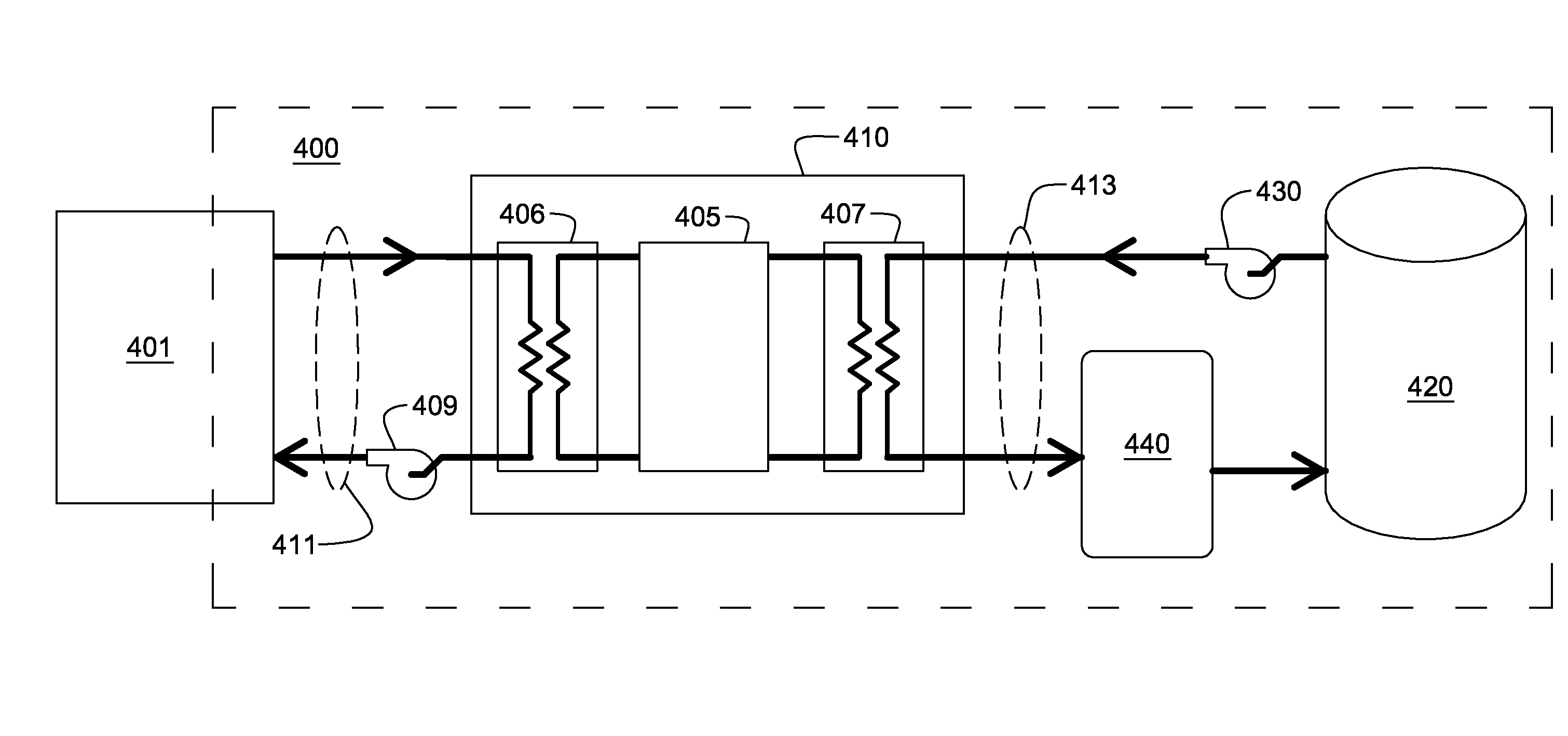
[0005]In another aspect, a cooled electronics system is provided which includes at least one electronics rack comprising at least one electronics unit, and a cooling system. The cooling system includes at least one facility cooling unit, a cooling tower and at least one thermal capacitor unit. The facility cooling unit includes a heat dissipation coolant loop. When operational, the facility cooling unit facilitates extracting thermal energy from the at least one electronics unit of the at least one electronics rack and expels the extracted thermal energy to coolant of the heat dissipation coolant loop. The cooling tower is in fluid communication with the heat dissipation coolant loop and includes a liquid-to-air heat exchanger for expelling thermal energy from coolant of the heat dissipation coolant loop to the surrounding environment. The at least one thermal capacitor unit is also in fluid communication with the heat dissipation coolant loop to facilitate efficient thermal energy transfer from coolant of the heat dissi...

Problems solved by technology

Undesirably, the efficiency of the cooling system is thus low during the day, when the data center, office or manufacturing f...

Method used


Image

  • Cooling system and method utilizing thermal capacitor unit(s) for enhanced thermal energy transfer efficiency
  • Cooling system and method utilizing thermal capacitor unit(s) for enhanced thermal energy transfer efficiency
  • Cooling system and method utilizing thermal capacitor unit(s) for enhanced thermal energy transfer efficiency

Examples


Embodiment Construction

[0017]As used herein, the terms “electronics rack”, “rack-mounted electronic equipment”, and “rack unit” are used interchangeably, and include any housing, frame, rack, compartment, blade server system, etc., having one or more heat generating components of a computer system or electronics system, and may be, for example, a stand alone computer processor having high, mid or low end processing capability. In one embodiment, an electronics rack may comprise multiple electronics drawers each having one or more heat generating components disposed therein requiring cooling. Further, as used herein, “liquid-to-air heat exchange unit” or “liquid-to-air heat exchanger” means any heat exchange mechanism characterized as described herein through which liquid coolant can circulate; and includes, one or more discrete liquid-to-air heat exchangers coupled either in series or in parallel. A liquid-to-air heat exchanger may comprise, for example, one or more coolant flow paths, formed of thermally...


PUM


Abstract

A cooling system and method are provided which include a facility cooling unit, a cooling tower, and one or more thermal capacitor units. The facility cooling unit, which includes a heat dissipation coolant loop, facilitates thermal energy extraction from a facility, such as a data center, for expelling of the energy to coolant within the heat dissipation coolant loop. The cooling tower is in fluid communication with the coolant loop, and includes a liquid-to-air heat exchanger for expelling thermal energy from coolant of the heat dissipation coolant loop to the surrounding environment. The thermal capacitor unit is in fluid communication with the heat dissipation coolant loop to facilitate efficient thermal energy transfer from coolant with in the coolant loop to the surrounding environment with variation in ambient temperature about the cooling tower.

Description

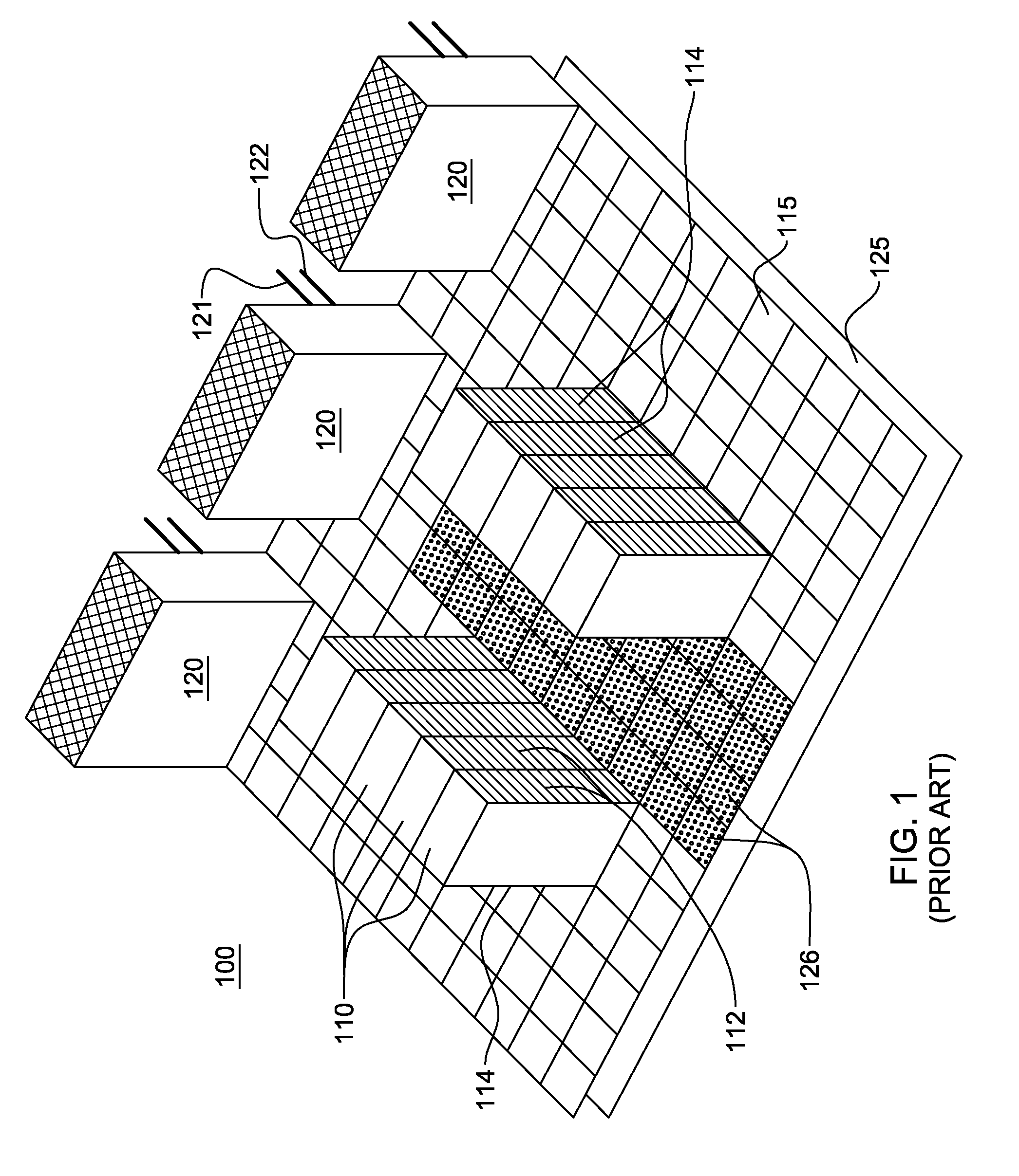
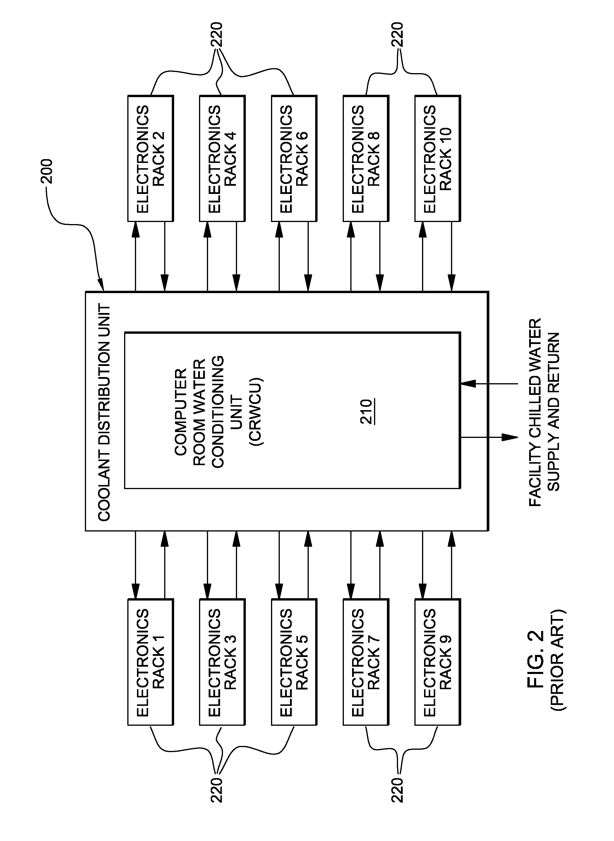
TECHNICAL FIELD OF THE INVENTION[0001]The present invention relates in general to cooling systems and methods, and more particularly, to cooling systems and methods for dissipating thermal energy from a facility such as a data center comprising one or more electronics racks. Still more particularly, the present invention relates to cooling systems and methods employing one or more thermal capacitor units for passively or actively maintaining coolant in a heat dissipation coolant loop within a defined range for a period of time with variation in ambient temperature about a cooling tower through which thermal energy of the coolant is dissipated.BACKGROUND OF THE INVENTION[0002]Cooling of data centers, as well as office complexes and manufacturing facilities, is typically achieved by coupling, for example, a vapor-compression refrigeration system to a heat dissipation coolant loop, such as a chilled water circulation loop. The ultimate heat rejection sink for the vapor-compression refr...

Claims


Application Information

Patent Timeline
IPC IPC(8): F28C1/00F28D15/00H05K7/20
CPCF24F5/0017F28D20/021H05K7/2079H05K7/20836Y02E60/145Y02E60/147Y02E60/14F28D20/02F24F5/00F28C1/00
Inventor CAMPBELL, LEVI A.CHU, RICHARD C.ELLSWORTH, JR., MICHAEL J.IYENGAR, MADHUSUDAN K.SIMONS, ROBERT E.
Owner IBM CORP
Why Eureka
Try Eureka