Thermal energy transfer limited rotating shaft for a pneumatic fan drive system

a technology of rotating shaft and fan drive, which is applied in the direction of mechanical actuated clutches, machines/engines, interlocking clutches, etc., can solve the problems of reducing the operating efficiency and life of the bearing, affecting the efficiency of the bearing, and affecting the bearing life, so as to reduce the amount of thermal energy, and improve the effect of thermal energy transfer

Active Publication Date: 2006-05-11
BORGWARNER INC
View PDF16 Cites 9 Cited by
  • Summary
  • Abstract
  • Description
  • Claims
  • Application Information

AI Technical Summary

Benefits of technology

[0008] The embodiments of the present invention provide several advantages. One such advantage is the provision of a rotating shaft having a thermal energy transfer portion that transfers an increased amount of thermal energy to a drive pulley of a clutch assembly. In so doing, the rotating shaft limits and minimizes the amount of thermal energy that is transferred to internal clutch bearings.
[0009] Another advantage provided by an embodiment of the present invention is the provision of a rotating shaft having a thermal energy transfer portion with a shaft width that is approximately equal to or greater than a shaft contact surface area width of a drive pulley. This provides efficient thermal energy transfer between the shaft and the pulley, which “pinches off” or minimizes the amount of thermal energy that is transferred to internal clutch bearings.
[0010] Yet another advantage provided by another embodiment of the present invention is the provision of a rotating shaft having a thermal energy transfer portion with one or more corresponding grooves that have a total groove width that is approximately equal to or greater than a shaft contact surface area width of a drive pulley. This also provides efficient thermal energy transfer between the shaft and the pulley, which also minimizes the amount of thermal energy that is transferred to internal clutch bearings.
[0011] Furthermore, the present invention provides an improved clutch assembly that is simple in design and cost effective.

Problems solved by technology

This passage of thermal energy to the internal bearings can degrade the bearings over time and is thus undesirable.
The thermal energy transfer between the shaft and the bearings increases the operating temperature of the bearings, which in turn causes the breakdown of bearing lubricant or grease and decreases the operating efficiency and life of the bearings.

Method used


Image

  • Thermal energy transfer limited rotating shaft for a pneumatic fan drive system
  • Thermal energy transfer limited rotating shaft for a pneumatic fan drive system
  • Thermal energy transfer limited rotating shaft for a pneumatic fan drive system

Examples


Embodiment Construction

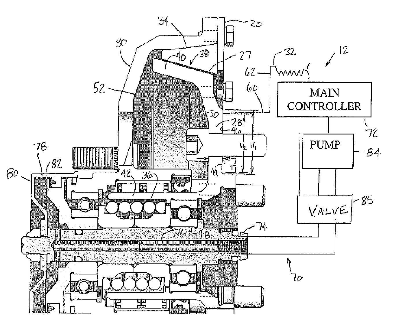
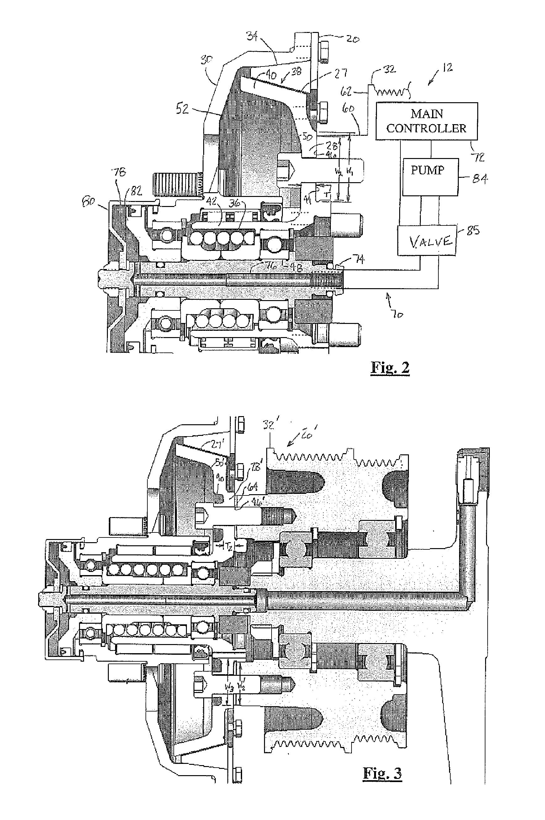
[0017] In the following figures the same reference numerals will be used to refer to the same components. While the present invention is described primarily with respect to a system for preventing the flow of thermal energy generated within a clutch interface area from passing to internal clutch bearings within a pneumatically controlled fan drive system, the present invention may be adapted and applied to various systems including: hydraulic systems, electrical systems, pneudraulic systems, mechanical systems, pneumatic systems, vehicle systems, cooling systems, fan drive systems, friction drive systems, or other systems.

[0018] In the following description, various operating parameters and components are described for one constructed embodiment. These specific parameters and components are included as examples and are not meant to be limiting.

[0019] Also, in the following description various fan drive components and assemblies are described as an illustrative example. The fan dri...


PUM


Abstract

A clutch assembly (20) for a fan drive system (12) of an engine (14) includes a translatable clutch housing (30) that is coupled to a fan (16). A rotating shaft (27) has a non-grooved thermal energy transfer portion (28) that is coupled to a drive pulley (32) of the engine (14). A liner (34) resides between and is engageable with the rotating shaft (27) and the translatable clutch housing (30). The engagement thereof generates thermal energy. The non-grooved thermal energy transfer portion (28) has a cross-sectional thickness (T1) of approximately less than 11 mm and transfers a significant portion of the thermal energy to the drive pulley (32).

Description

TECHNICAL FIELD [0001] The invention relates generally to fan drive systems and more specifically to reducing the flow of thermal energy generated within a clutch interface area from passing to internal clutch bearings within a pneumatically controlled fan drive system. BACKGROUND ART [0002] The present invention relates to friction coupling devices that drive radiator cooling fans. A common friction coupling device is that of the dry friction drive style. Dry friction drives are used for their simplicity, cool operating temperature, and ability to turn at fully engaged peak operating speeds. [0003] Although the present invention may be used advantageously in various configurations and applications, it is especially advantageous in a coupling device of the type used to drive a radiator cooling fan of an internal combustion engine for a over the road truck, such as a class 8 truck, and will be described in connection therewith. [0004] Dry friction drives tend to have two operating co...

Claims


Application Information

Patent Timeline
Patent Type & Authority Applications(United States)
IPC IPC(8): F16D13/24F16D13/72
CPCF01P1/06F01P7/082F16D25/0632F16D25/123
Inventor SETTINERI, SAMUEL E.
Owner BORGWARNER INC
Why Eureka
Try Eureka