
LCD heater system

a heater system and liquid crystal display technology, applied in non-linear optics, instruments, optics, etc., can solve the problems of poor visual clarity, inconvenient operation of lcd, and high cost of ito film, and reduce the manufacturing steps and time involved, reducing the potential for glass degradation, and efficient heating of fpd

Inactive Publication Date: 2006-10-05
LEAR CORP
View PDF5 Cites 8 Cited by
  • Summary
  • Abstract
  • Description
  • Claims
  • Application Information

AI Technical Summary

Benefits of technology

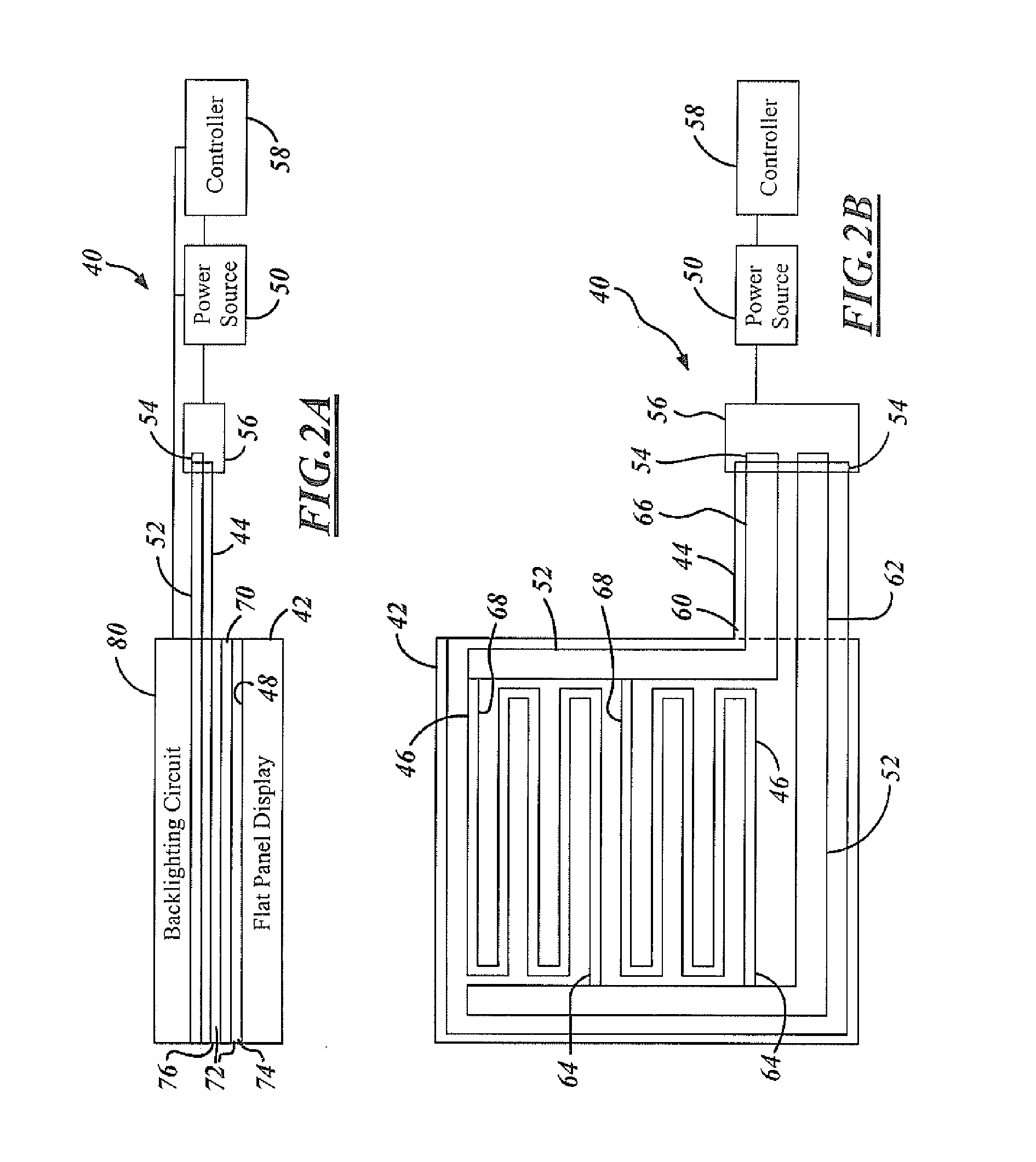
[0010] The embodiments of the present invention provide several advantages. One such advantage is the provision of a flexible circuit coupled to an FPD. The incorporation of the flex circuit allows for efficient heating of the FPD. The application of a flex circuit to an FPD reduces manufacturing steps and time involved therein due to the application of a single thermal energy transfer layer to an FPD. A flex circuit provides a relatively thin and lightweight thermal energy transfer medium. The incorporation of a flex circuit also eliminates the need to screen ITO films or the like to the glass of an FPD, thereby, minimizing the potential for glass degradation. In addition, the use of a flex circuit minimizes light transmission degradation. The flex circuit is relatively thin in comparison to stacked layers of ITO film and this allows for an increased amount of backlighting to pass through an FPD.
[0011] Another advantage provided by an embodiment of the present invention is the provision of an FPD assembly that has a flex circuit with traces that are formed of a highly conductive material. The traces allow for efficient thermal energy transfer to and quick temperature increases of an FPD.

Problems solved by technology

Below approximately 10° C. the reaction of the liquid crystals tends to slow down and thus the LCD may operate inappropriately and / or have poor visual clarity.
ITO films are considered expensive and can have associated functional disadvantages.
Since indium tin oxide is generally a poor electrical conductor a significant amount of current must be applied to the ITO layers to increase the temperature of the LCD within the desired time frame.
The process of applying the ITO film is considered costly and time consuming, especially due to the number of layers that must be applied.
Also, since the ITO film is screened onto the glass, degradation to the glass can occur in the screening process.
In addition, the thicker the ITO film the less the amount of light that can be transmitted through the LCD, resulting in performance and clarity degradation.

Method used


Image

  • LCD heater system
  • LCD heater system
  • LCD heater system

Examples


Embodiment Construction

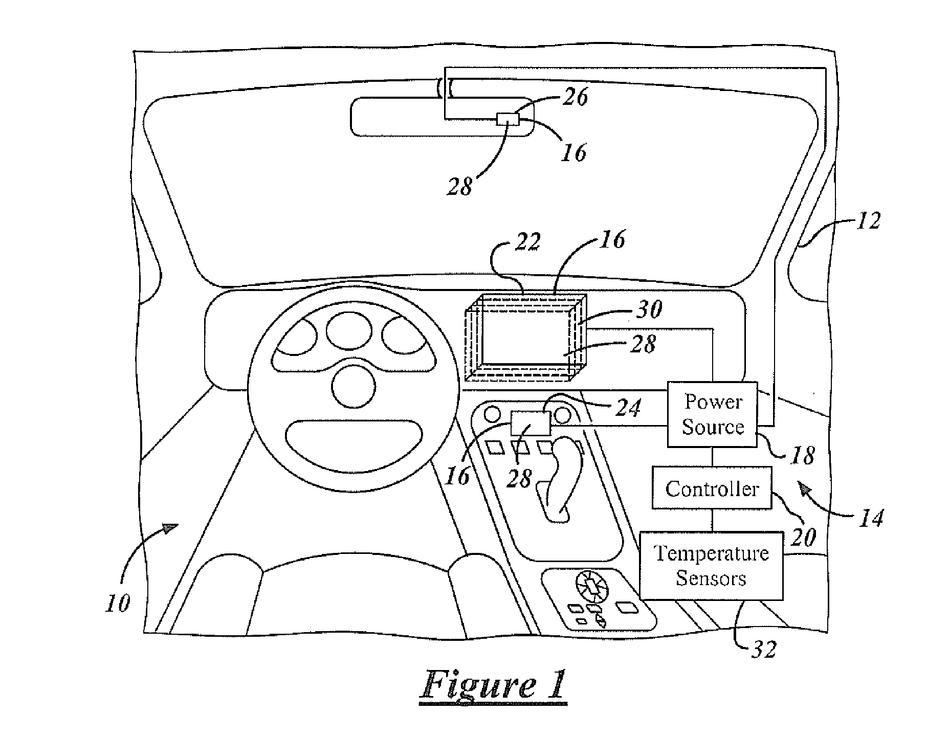
[0018] While the present invention is described primarily with respect to an LCD heater system and method of manufacturing the same, the present invention may be adapted to various flat panel displays having heating requirements. The present invention may be applied to displays within ground-based vehicles, aeronautical vehicles, watercraft, and to other vehicle and non-vehicle applications. The present invention may be applied to navigation system displays, audio and video displays, computer displays, rear view mirror displays, dashboard displays, console displays, instrument panel displays, as well as to other displays known in the art.

[0019] In the following description, various operating parameters and components are described for one constructed embodiment. These specific parameters and components are included as examples and are not meant to be limiting.

[0020] Referring now to FIG. 1, a perspective view of interior cabin 10 of a vehicle 12 incorporating flat panel display (F...


PUM

PropertyMeasurementUnit
temperatureaaaaaaaaaa
metallicaaaaaaaaaa
currentaaaaaaaaaa

Abstract

A flat panel display assembly (16) includes a flat panel display (28) and a heater (30). The heater (30) includes a heating trace (46) that is attached to and heats the flat panel display (28). A method of fabricating a flat panel display assembly includes forming a flat panel display (28). A flex circuit (30) with a heating trace (46) is applied to the flat panel display (28). Electrical conductors (52) are coupled to the heating trace (46) for current supply therethrough.

Description

TECHNICAL FIELD [0001] The present invention relates to liquid crystal displays (LCDs) and the like and more particularly, to a technique for heating the same. BACKGROUND OF THE INVENTION [0002] LCDs are utilized throughout industry for various purposes. With respect to the automotive industry, LCDs are often used to display information to a vehicle occupant. An LCD may, for example, be used to display navigation information or audio / video information. [0003] An LCD typically consists of a pair of polarized panels with liquid crystals therebetween. The polarizing panels and the liquid crystals are applied to a piece of glass, which is mounted on a mirror or reflective substance. As an electric charge is applied to the liquid crystals they untwist allowing light to pass through the crystals. The amount of electric charge applied to the crystals adjusts the amount of light that is permitted to pass through the LCD. In operation, light passes through the first polarizing panel and the ...

Claims


Application Information

Patent Timeline
Patent Type & Authority Applications(United States)
IPC IPC(8): G02F1/1333
CPCG02F1/133382G02F1/13452G02F1/1336G02F1/133504
Inventor HEIN, DAVID A.SCHMIDT, ROBERT M.
Owner LEAR CORP
Learn More