Apparatus for textile counting, sorting and classifying system

a technology for textile counting and classification systems, applied in the field of textile sorting machines, can solve the problems of increasing power requirements, and achieve the effect of reducing the suction requiremen

Inactive Publication Date: 2008-12-18
COLMAC INDS
View PDF3 Cites 10 Cited by
  • Summary
  • Abstract
  • Description
  • Claims
  • Application Information

AI Technical Summary

Benefits of technology

[0014]The first counting / sorting portion of the system does not use the damper or blast gate 80 (FIG. 9) method for controlling vacuum to the bin. A variable frequency drive unit (VFD) 62 (FIG. 10) having a brake 25 (FIG. 10) is used to quickly start and stop the motor 26 to control vacuum generated by fan 24. When the dump cycle from the sorting bin is initiated, the VFD shuts down the motor very quickly to eliminate all suction and allow the goods to drop. The braking mechanism 25 is employed to stop the motor even more quickly. This allows the system to save electrical power while the system is in dump mode. Also, the system controls the motor so that during non-sorting operations (when textiles are not actively being delivered) the motor is off, unlike previous systems where the motor was more or less operating continuously for an entire work shift. During this downtime, the laundry is spared from unnecessary noise as well. When counting / sorting resumes, the motor is ramped up to speed with a gradual curve, to avoid large current inrush, which could trigger “Demand” charges by some electric utility providers.
[0015]The second, “classifier” portion of the system overcomes the high power requirements of previous systems. The system uses the vacuum side of the motor(s) for all bins, but has unique design advantages. In order for a bin to create suction, but not self-plug the inlet with the textiles themselves, prior systems required either large internal volumes, or baffles that restricted flow, thus increasing power requirements. The present sorting system uses a cyclonic principle in which the textile goods, or workpiece, enter a cone-shaped bin at high velocity. In the cone-shaped bin the workpiece travels in a spiraling motion whereupon the velocity is dissipated and the workpiece falls to the bottom of the bin away from the suction inlet.
[0018]One present embodiment has a gradually downward path of the receiving arm into the cyclonic bin. This reduces the suction requirement to move the textile goods. The inlet angle of the receiving arm to the sorting bin, is generally in a tangential alignment to the side of the cone. This is the beginning of the circular vortex path of the textile item within the sorting bin during which the textile item falls out of the suction path and drops toward the conical sorting bin apex.
[0019]Another aspect of the cyclonic vortex bin is the suction motor control. Similar to the conventional bin previously described, the motor can be controlled by a variable frequency drive unit (VFD). The benefits of stopped operation when there is no suction demand, and gradual start-stop of the motor for avoiding utility (“Demand”) charges are realized. The system also uses a monitoring control to determine the number of suction tubes in operation. When fewer tubes are in operation, the operational rate of the motor can be correspondingly reduced, saving energy and optimizing the suction necessary. When the number of tubes in use is larger, or at maximum for the system size, the flow rate can be increased, optimizing the necessary suction. Thus the required energy can be matched to the suction needed.

Problems solved by technology

In order for a bin to create suction, but not self-plug the inlet with the textiles themselves, prior systems required either large internal volumes, or baffles that restricted flow, thus increasing power requirements.
This caused an undesirable problem: “blow-by”, where the goods would not slow and direct to the desired bin, but coast on past the inlet.

Method used


Image

  • Apparatus for textile counting, sorting and classifying system
  • Apparatus for textile counting, sorting and classifying system
  • Apparatus for textile counting, sorting and classifying system

Examples


Embodiment Construction

[0032]As required, detailed embodiments of the present inventions are disclosed herein; however, it is to be understood that the disclosed embodiments are merely exemplary of the invention, which may be embodied in various forms. Therefore, specific structural and functional details disclosed herein are not to be interpreted as limiting, but merely as a basis for the claims and as a representative basis for teaching one skilled in the art to variously employ the present invention in virtually any appropriately detailed structure.

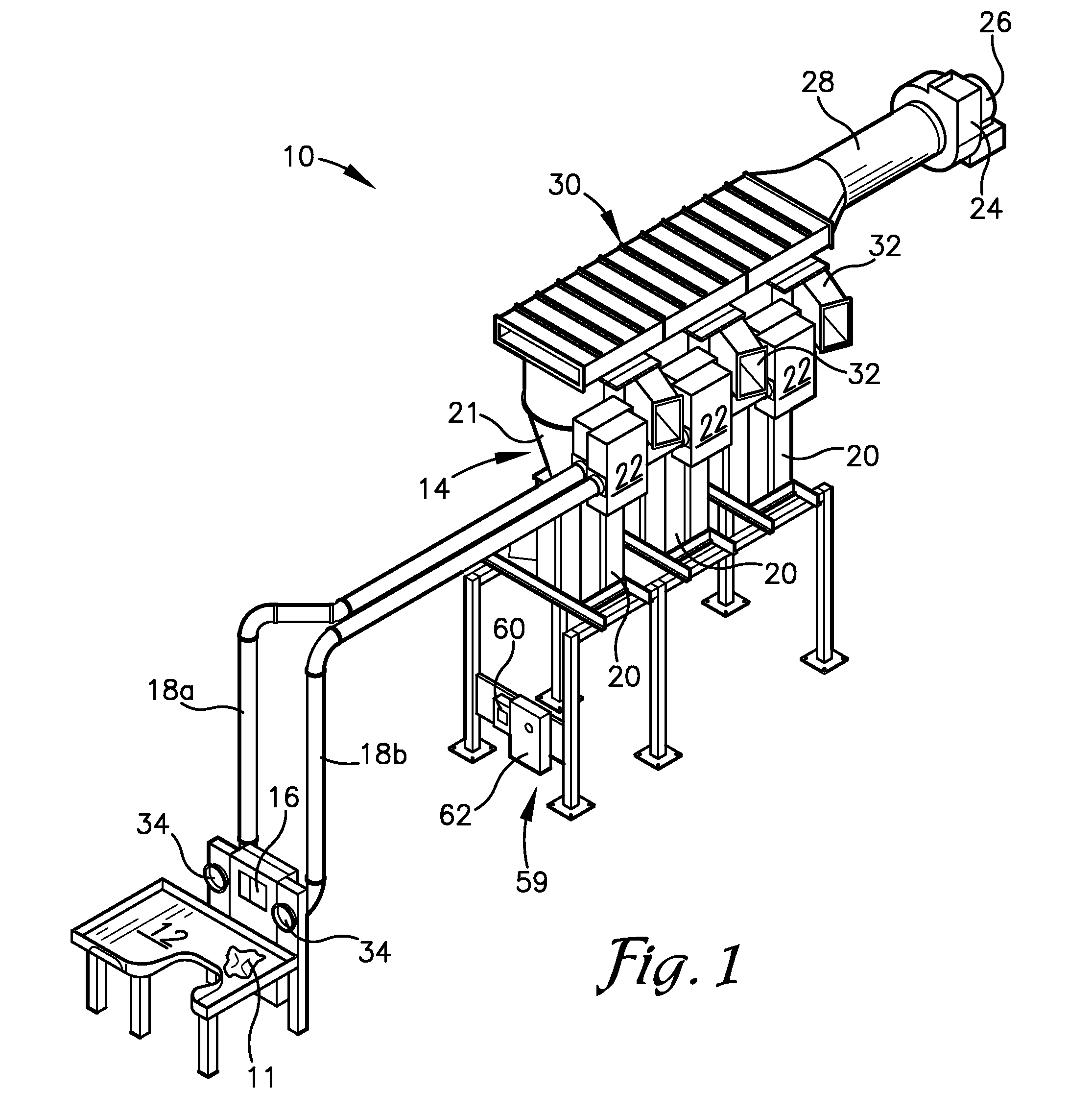
[0033]First referring to FIG. 1, a perspective top and right side view of the overall apparatus 10 is shown. The structure of the apparatus 10 will now be described in the sequence that a textile article or workpiece 11 would take in passing through the apparatus 10. The soiled textile is first deposited onto a soil counting table or work table 12 where an operator sorts the workpiece from other textile workpieces and determines which sorting bin 14 the part...


PUM


Abstract

An apparatus is provided for transporting textile items into sorting bins with reduced energy consumption and improved load measuring accuracy and which provides textile item counting and sorting for a commercial laundry using vacuum air systems to move textiles into sorting bins and using a variable frequency drive to increase on / off response time of vacuum in the system.

Description

CROSS REFERENCE TO RELATED APPLICATION[0001]This application claims priority under 35 U.S.C. 119(e) and 37 C.F.R. 1.78(a)(4) based upon copending U.S. Provisional Application Ser. No. 60 / 936,064 for Energy Reduction Apparatus For Soiled Textile Sortation System filed Jun. 18, 2007 and the specification of which is incorporated herein by reference.FIELD OF THE INVENTION[0002]The present apparatus is related to the field of textile sorting machines for use in commercial laundries and the like. More particularly, the present apparatus provides a more energy efficient all suction-based textile flow pathway apparatus that allows for counting and sorting and classifying and dividing textiles into groups prior to the distribution of the textile groups about a laundry operation for further actions thereon. The apparatus further provides selectable control of the amount of suction delivered to the apparatus in response to the amount of usage the system is receiving.BACKGROUND OF THE INVENTIO...

Claims


Application Information

Patent Timeline
Patent Type & Authority Applications(United States)
IPC IPC(8): B07C5/00
CPCD06F93/00Y10S209/942Y10S209/937
Inventor OSIENSKY, BRANT R.RINELLA, DAVIDPELISSIER, GERALD W.MCMILLAN, SCOTT
Owner COLMAC INDS
Why Eureka
Try Eureka