Steel-plate electric flat carriage control device

An electric flat car and control device technology, applied in the direction of AC induction motor traction, etc., can solve the problems of poor insulation, large grounding voltage drop, and high electrical failure rate, and achieve simple and controllable lines, less voltage drop, and easy operation. Effect

Inactive Publication Date: 2017-05-17
SD STEEL RIZHAO CO LTD
View PDF6 Cites 2 Cited by
  • Summary
  • Abstract
  • Description
  • Claims
  • Application Information

AI Technical Summary

Problems solved by technology

[0003] The current electric flat car device has certain technical disadvantages and potential safety hazards: 1. The existing method is that the transformer reduces the voltage of 380v to 36v, and then taps it to two tracks, and the track flat car passes through the power-taking legs on the track. Power is taken from the power supply, and the 36V power supply on the rail is introduced into the vehicle electrical box. Often due to poor insulation, grounding or a large voltage drop is caused, which affects the operating efficiency of the motor, and the motor will burn out if it works for a long time
2. The laying of the track is required to be no more than 50 meters. Once the running distance exceeds 50 meters, the secondary side voltage will drop seriously. It is necessary to increase the number of transformers and copper compensation lines to make up for the track voltage drop, resulting in an increase in cost
3. The AC 36V is rectified to DC 380V through the rectifier module, and the capacitor in the vehicle electrical box, the rectifier module or the isolation transformer often burn out, and the electrical failure rate is high

Method used


Image

  • Steel-plate electric flat carriage control device
  • Steel-plate electric flat carriage control device
  • Steel-plate electric flat carriage control device

Examples


Embodiment Construction

[0014] The present invention is described in further detail now in conjunction with accompanying drawing.

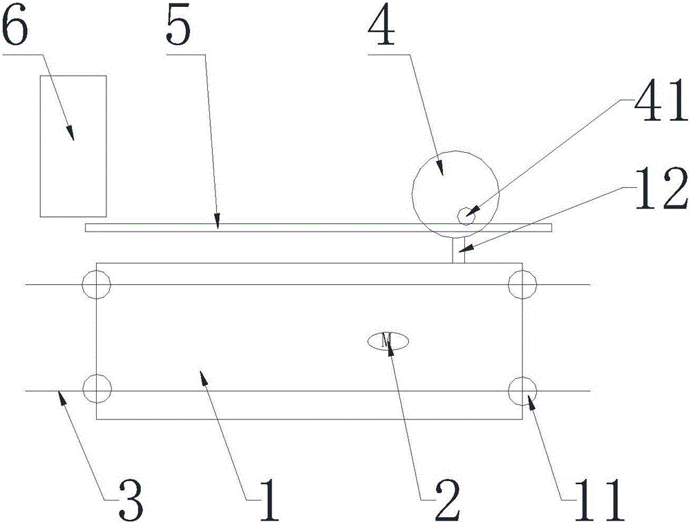
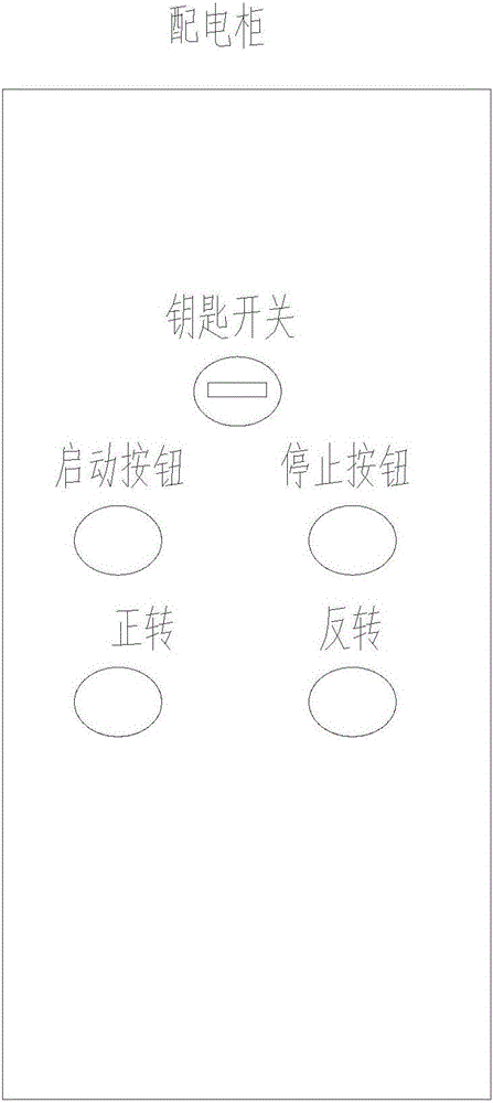
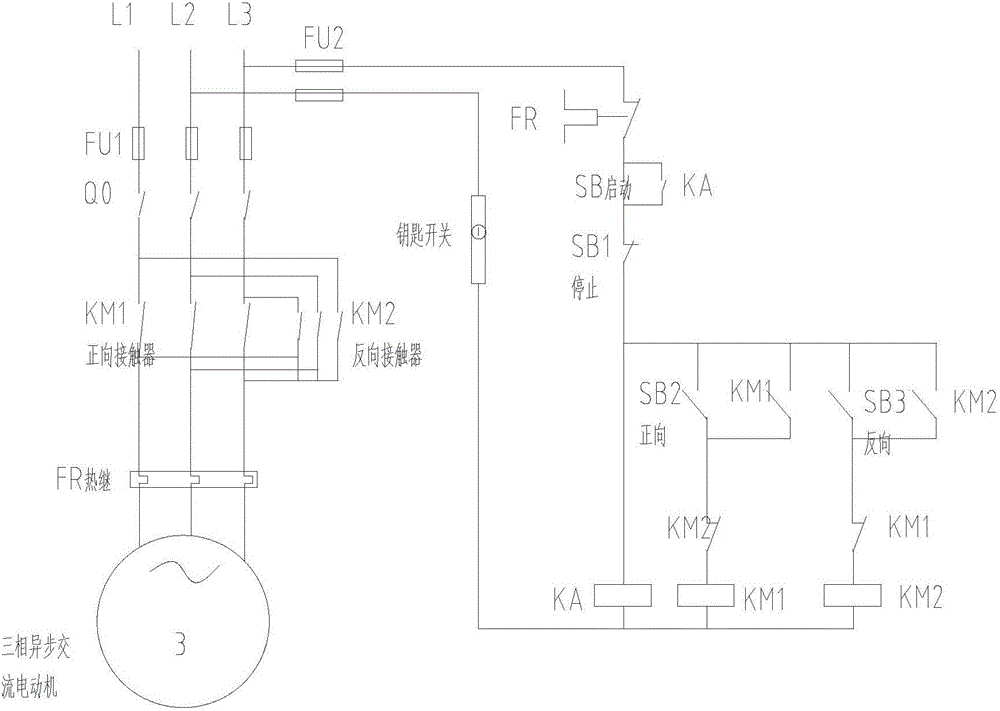
[0015] according to Figure 1 to Figure 3 The control device for a steel plate electric flat car includes an electric flat car 1, a track 3, and cables. The electric flat car 1 is assembled on the track 3 through wheels 11. The cable trench 5 is placed in the cable trench 5, and a cable bridge is placed in the cable trench 5. One end of the electric flat car 1 is provided with a steel structure support 12, and a spring type cable reel 4 is provided on the steel structure support 12. One end of the cable is connected to the distribution cabinet 6, the three-phase electrical connection, the free end of the cable is wound in the cable reel 4, after the rotating slip ring 41 of the cable reel 4 is exposed, it is electrically connected with the three-phase AC asynchronous motor 2, so that the electric flat car 1 moves During the process, the cable wound in the cable reel 4 c...


PUM


Abstract

The invention relates to a steel-plate electric flat carriage control device which comprises an electric flat carriage, a track and a cable. The electric flat carriage is assembled on the track through wheels, a cable duct mutually parallel to the track is arranged beside the track, a cable bridge is put in the cable duct, a steel structure support is arranged at one end of the electric flat carriage, a spring-type cable drum is arranged on the steel structure support, one end of the cable is electrically connected with three-phase current of a power distribution cabinet, the free end of the cable is wound in the cable drum, and a rotary sliding ring of the cable drum is exposed and then is electrically connected with a three-phase alternating-current asynchronous motor. The cable of the device can move together with the electric flat carriage, the cable outside the cable drum rightly falls into the cable duct, the alternating-current asynchronous motor of the electric flat carriage is connected with the power distribution cabinet through the cable, and rapid start and stop of the three-phase alternating-current asynchronous motor are achieved. The steel-plate electric flat carriage control device is simple, controllable and convenient to operate. Due to the fact that a power supply is low-voltage 380 V, voltage drop is small, and the shortcomings of an original electric flat carriage can be overcome.

Description

technical field [0001] The invention relates to the field of transportation and collection at the rear of an electric flat car rolling line, in particular to a control device for a steel plate electric flat car. Background technique [0002] Improving the transportation efficiency of steel plates and reducing equipment failures is one of the important ways to improve production efficiency and reduce production costs. [0003] The current electric flat car device has certain technical disadvantages and potential safety hazards: 1. The existing method is that the transformer reduces the voltage of 380v to 36v, and then taps it to two tracks, and the track flat car passes through the power-taking legs on the track. Power is taken from the power supply, and the 36V power supply on the rail is introduced into the vehicle electrical box. Often due to poor insulation, grounding or a large voltage drop is caused, which affects the operating efficiency of the motor, and the motor wil...

Claims


Application Information

Patent Timeline
Patent Type & Authority Applications(China)
IPC IPC(8): B60L9/24
CPCB60L9/24
Inventor 何敬秋吴晓光郭靖吴涛刘德红宋光鑫张子义徐淑涛王涛
Owner SD STEEL RIZHAO CO LTD
Why Eureka
Try Eureka