Simplified powder feeding and vaporization apparatus

a powder feeding and vaporization apparatus technology, applied in vacuum evaporation coatings, chemical vapor deposition coatings, coatings, etc., can solve the problems of increasing the difficulty of precise metering of small amounts of powdered materials, and the use of additives. achieve the effect of reducing the risk of degrading, reducing the risk of contamination, and increasing the vaporization ra

Inactive Publication Date: 2010-08-19
GLOBAL OLED TECH
View PDF32 Cites 2 Cited by
  • Summary
  • Abstract
  • Description
  • Claims
  • Application Information

AI Technical Summary

Benefits of technology

[0024]It is an advantage of this invention that it can provide adjustable controlled metering and vaporization of small quantities of particulate material more uniformly than many prior art devices. The particulate material transport apparatus of the present invention can accurately deliver small amounts of particulate material such as 1 microgram per second, as well as much larger amounts, such as up to 1000 micrograms per second. It is a further advantage of the present invention that it can meter particulate materials uniformly without the use of a carrier, such as an inert gas, liquid or solid. It is a further advantage of the present invention that it can maintain a steady vaporization rate with a continuously replenished charge of particulate material and with no heater temperature change required as the source material is consumed. It is a further advantage of the present invention that the particulate material is maintained at lower temperature in the material reservoir and is heated only as it is discharged into the associated vaporizing chamber. The device permits extended operation of the source with substantially higher vaporization rates than in many prior art devices and has substantially reduced risk of degrading even very temperature-sensitive organic materials. It is a further advantage of the present invention that it can be used in a vaporization system for independently controlling multiple feed rates, such as dopant and host. It is a farther advantage of this invention that it permits rapid starting and stopping of vaporization. It is a further advantage of this invention that it can deliver controlled volumes of vapor and thereby control the deposited film thickness in area deposition processes. It is a further advantage of the present invention that it can provide a vapor source in any orientation, which is frequently not possible with prior-art devices.
that it can meter particulate materials uniformly without the use of a carrier, such as an inert gas, liquid or solid. It is a further advantage of the present invention that it can maintain a steady vaporization rate with a continuously replenished charge of particulate material and with no heater temperature change required as the source material is consumed. It is a further advantage of the present invention that the particulate material is maintained at lower temperature in the material reservoir and is heated only as it is discharged into the associated vaporizing chamber. The device permits extended operation of the source with substantially higher vaporization rates than in many prior art devices and has substantially reduced risk of degrading even very temperature-sensitive organic materials. It is a further advantage of the present invention that it can be used in a vaporization system for independently controlling multiple feed rates, such as dopant and host. It is a farther advantage of this invention that it permits rapid starting and stopping of vaporization. It is a further advantage of this invention that it can deliver controlled volumes of vapor and thereby control the deposited film thickness in area deposition processes. It is a further advantage of the present invention that it can provide a vapor source in any orientation, which is frequently not possible with prior-art devices.

Problems solved by technology

It is well known that precisely metering small amounts of powdered materials is difficult.
The use of any sort of additive increases the material transport complexity, for the carrier or additive needs to be added, removed, and handled separately from the actual material of interest.
The use of carriers also increases the risk of contamination, which is particularly detrimental in the pharmaceutical and electronics manufacturing industries where there is a particular need to meter materials.
Transporting a mixture that is mostly inert carrier effectively reduces the powder dispensing accuracy requirements by an order of magnitude if the mixture is homogeneous, but this method adds cost and complexity to the system and increases the potential for the introduction of contaminates into the material feed.
One of the problems with using this type of auger structure with powders is varying discharge rate.
Another problem with auger structures is that they are prone to jamming if the powder is not free flowing or tends to pack into a consolidated mass.
Their use with powders whose particle size is less than 50 microns tends to be problematic.
Additional difficulty is encountered if the powder-dispensing system is used to deliver powder to a vaporization process.
The difficulty in maintaining adjacent hot and cold regions is that vapor from the heated powder will condense on surfaces cooler than the vapor's condensation temperature and quickly foul most powder delivery systems.
The organic materials used for OLED devices are often subject to degradation when maintained at or near the desired rate-dependent vaporization temperature for extended periods of time.
Exposure of sensitive organic materials to higher temperatures can cause changes in the structure of the molecules and associated changes in material properties.
In this manner, the material is consumed before it has reached the temperature exposure threshold to cause significant degradation.
The limitations with this practice are that the available vaporization rate is very low due to the limitation on heater temperature, and the operation time of the source is very short due to the small quantity of material present in the source.
The low deposition rate and the frequent and time-consuming process associated with recharging a source has placed substantial limitations on the throughput of OLED manufacturing facilities.
A secondary consequence of heating the entire organic material charge to roughly the same temperature is that it is impractical to mix additional organic materials, such as dopants, with a host material unless the vaporization behavior and vapor pressure of the dopant is very close to that of the host material.
This gradient co-deposition is unavoidable in prior art sources where a different single material is vaporized from each of multiple sources directly onto a substrate.
However, none of these earlier teachings anticipates the need to have independent metering control for the host and dopant materials.
The transport mechanisms are therefore unable, by virtue of design, to meter at the low rates, 1-10 micrograms / second, required for an independent dopant feed.
These powder feeding pumps are intended for use with much larger particle size powders and are not adapted to metering powder on a milligram or microgram basis.

Method used


Image

  • Simplified powder feeding and vaporization apparatus
  • Simplified powder feeding and vaporization apparatus
  • Simplified powder feeding and vaporization apparatus

Examples


Embodiment Construction

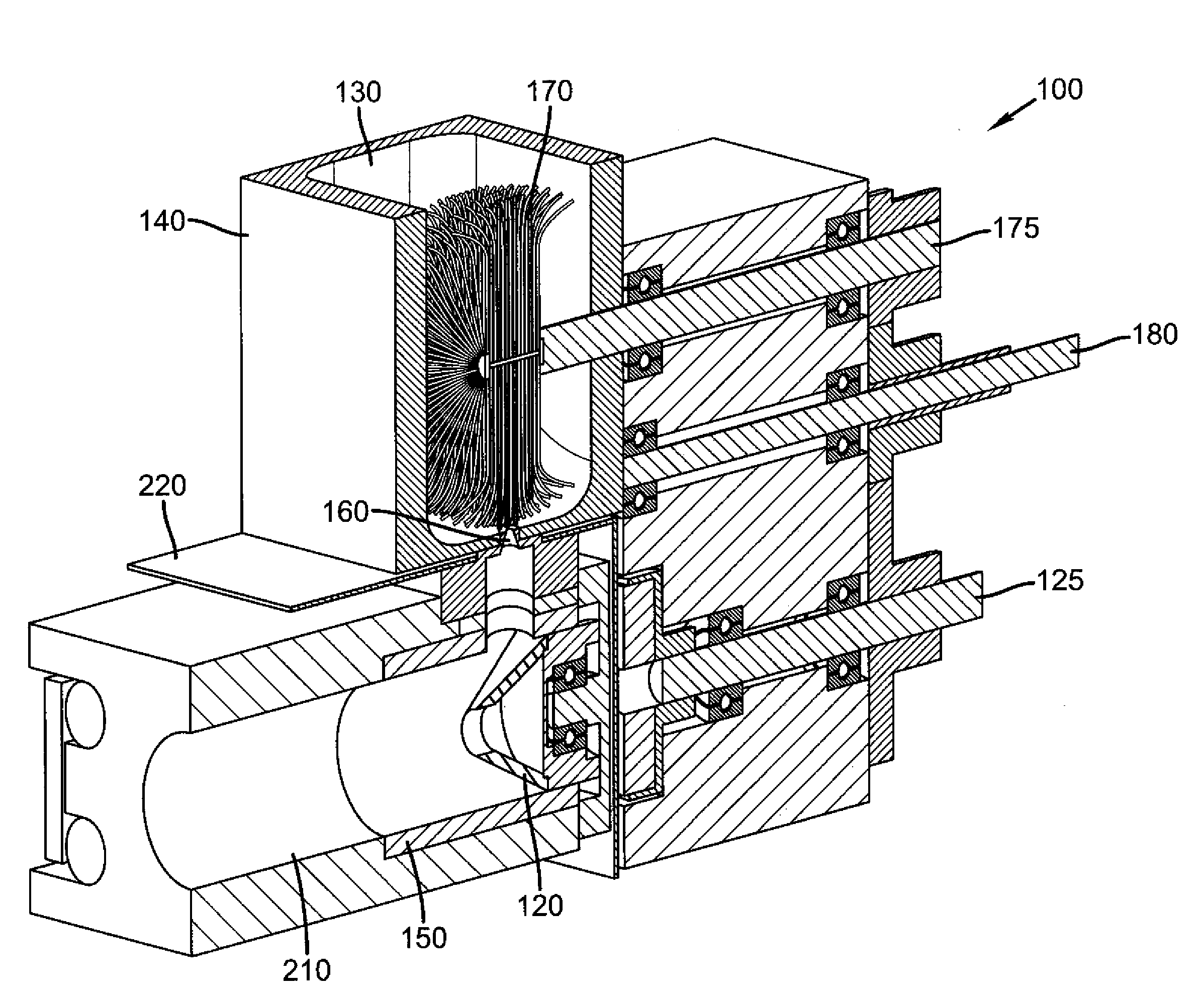
[0033]Turning now to FIG. 3, there is shown a three-dimensional cross-sectional view of one embodiment of an apparatus according to the present invention. Vaporizing apparatus 100 is an apparatus for vaporizing particulate material. Vaporizing apparatus 100 includes a metering apparatus, which includes a housing having a reservoir for receiving particulate material, an opening in the reservoir for discharging the material into a vaporizing chamber, and a rotatable wire brush wheel disposed in the reservoir. These components will be described in more detail. Reservoir 130 is in housing 140 and is for receiving particulate material. The particulate material can include a single component, or can include two or more different material components, each one having a different vaporization temperature. Although not shown, reservoir 130 can include a larger storage and feeding apparatus above it to increase the volume of particulate material that can be loaded. Such containers and feeding ...


PUM

PropertyMeasurementUnit
weight accuracyaaaaaaaaaa
particle sizeaaaaaaaaaa
lengthaaaaaaaaaa

Abstract

An apparatus for vaporizing a particulate material, including: a metering apparatus including: a reservoir for receiving particulate material; the reservoir having an opening for discharging the particulate material into a vaporizing chamber; a rotatable wire wheel brush disposed in the reservoir; wherein the dimensions of the reservoir and the wire wheel brush are selected so that the wire wheel brush cooperates with the interior walls of the reservoir to fluidize the particulate material and wherein a metered portion of the particulate material is entrained in the tines of the wire wheel brush and subsequently forcefully released into the reservoir opening; and a flash evaporator that receives and vaporizes the metered material.

Description

CROSS REFERENCE TO RELATED APPLICATIONS[0001]Reference is made to commonly assigned U.S. patent application Ser. No. 12 / 271,211, filed Nov. 14, 2008, by Long et al.; the disclosures of which are incorporated herein by reference.FIELD OF THE INVENTION[0002]The present invention relates to metering of particulate materials, over a large range of feed rates, into a vaporization apparatus.BACKGROUND OF THE INVENTION[0003]There is a need to be able to dispense small quantities of finely divided powders with high weight or volume accuracy for batch processes operating in a vacuum. There is also a need to dispense powders in a continuous stream with a high accuracy and consistency in the dispensing rate for continuous processes operating in a vacuum. For some processes, for example, the weight accuracy necessary is plus or minus 10 micrograms and the rate consistency is plus or minus 10 micrograms per second.[0004]The electronics industry in particular has a need to meter small quantities ...

Claims


Application Information

Patent Timeline
Patent Type & Authority Applications(United States)
IPC IPC(8): C23C16/00
CPCC23C14/246C23C14/12C23C14/24
Inventor LONG, MICHAEL
Owner GLOBAL OLED TECH
Why Eureka
Try Eureka