Method and Installation for Connecting a Rigid Submarine Pipe and a Flexible Submarine Pipe

a technology of rigid submarine pipes and flexible pipes, applied in the direction of hose connections, borehole/well accessories, mechanical devices, etc., can solve the problems of free connection end movement, intrinsic longitudinal deformation, longitudinal deformation, etc., and achieve the effect of preventing working

Active Publication Date: 2008-12-18
TECH FRANCE SA
View PDF17 Cites 7 Cited by
  • Summary
  • Abstract
  • Description
  • Claims
  • Application Information

AI Technical Summary

Benefits of technology

[0009]A problem that then arises and that the present invention aims to solve is to propose a connection method that makes it possible to dispense with the aforementioned disadvantages and particularly that makes it possible to prevent working at great depth.

Problems solved by technology

However, in certain operating circumstances, the temperature variations of the extracted hydrocarbon cause longitudinal deformations of the rigid pipe and as a result the movement of the free connection end.
Consequently, the flow-line portion of the flexible pipe that lies between the free connection end of the rigid pipe and the anchor point is likely to be moved in translation on the seabed, which on the one hand causes its intrinsic longitudinal deformation and, on the other hand its abrasion.
Now, when the rigid pipe retracts, particularly when the flow of hydrocarbon is stopped and the pipe cools, the retraction forces oppose the pulling forces exerted by the flexible pipe, so that the rigid pipe risks being damaged.
Although it was feasible before, for shallow and medium-depth submarine installations, to work easily on the damaged rigid pipe, this work is no longer feasible for submarine installations at very great depths.

Method used


Image

  • Method and Installation for Connecting a Rigid Submarine Pipe and a Flexible Submarine Pipe
  • Method and Installation for Connecting a Rigid Submarine Pipe and a Flexible Submarine Pipe
  • Method and Installation for Connecting a Rigid Submarine Pipe and a Flexible Submarine Pipe

Examples


Embodiment Construction

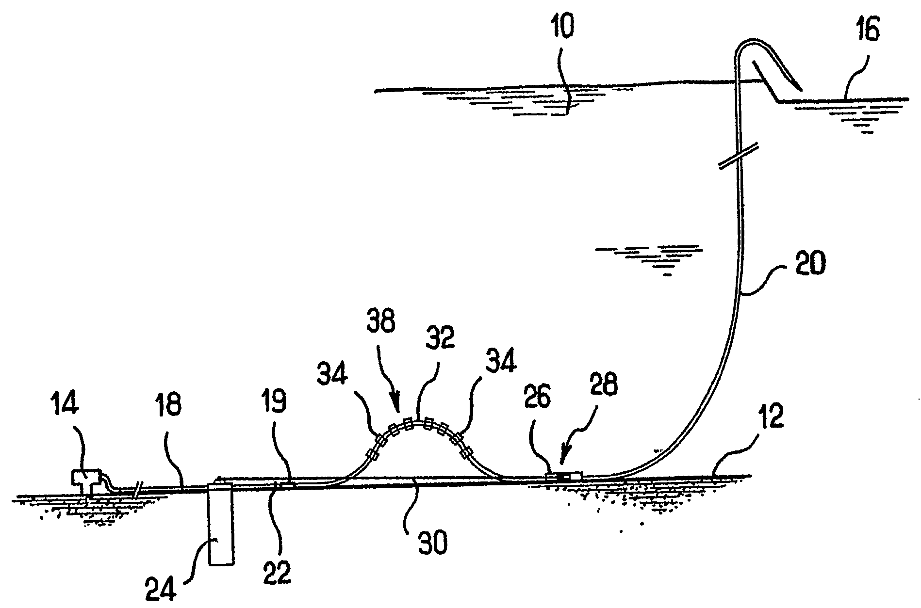
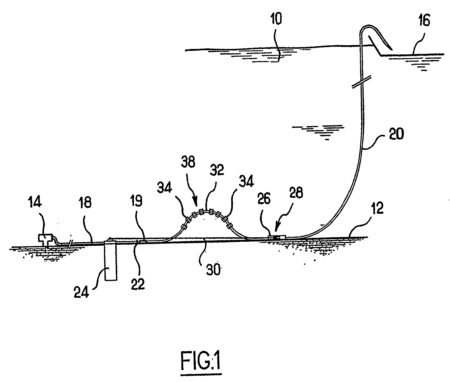
[0024]FIG. 1 shows schematically and in vertical section a marine environment having a surface 10 and a bed 12. A submarine installation 14 installed on the bed 12 is designed for the extraction of a hydrocarbon. A surface installation 16 is designed to recover and store a hydrocarbon. Between the submarine installation 14 and the surface installation 16, a rigid pipe 18 lies on the seabed 12 and extends from the submarine installation 14. A flexible pipe 20 is connected to the rigid pipe by an input end 19 and extends the rigid pipe and then joins to the surface installation 16. Together these elements make it possible to recover the hydrocarbon.

[0025]The rigid pipe 18 has a free connection end 22. It is capable of deforming longitudinally under the effect of the variations of pressure of the hydrocarbon and / or of temperature of the pipe caused by the flow variations of a hydrocarbon that is hotter than the temperature of the marine environment at the seabed 12. Consequently, durin...


PUM

PropertyMeasurementUnit
flexibleaaaaaaaaaa
lengthaaaaaaaaaa
distanceaaaaaaaaaa

Abstract

A method and an installation for connecting a rigid submarine pipe and a flexible submarine pipe. The rigid pipe terminates in a free connection end. The flexible pipe has a flow-line portion and a suspended portion. The flow-line portion has an input end connected to the free connection end. The installation comprises an anchoring device to hold the flow-line portion anchored at an anchor point and to allow the flow-line portion to form an undulation. The anchoring device is suitable for holding the anchor point at a distance and close to the free connection end to form the undulation between the anchor point and the free connection end.

Description

CROSS-REFERENCE TO RELATED APPLICATION[0001]The present application is a 35 U.S.C. §§ 371 national phase conversion of PCT / FR2006 / 001676, filed 10 Jul. 2006, which claims priority of French Application No. 0507382, filed Jul. 11, 2005. The PCT International Application was published in the French language.BACKGROUND OF THE INVENTION[0002]The present invention relates to a method for connecting a rigid submarine pipe and a flexible submarine pipe, and to an installation suitable for using this connection method.[0003]These submarine pipes are designed to transport hydrocarbons in a marine environment and in particular to carry the hydrocarbons between a submarine installation installed on the seabed and a surface marine installation, for example a platform situated on the surface of the marine environment.[0004]The rigid submarine pipe is extended over the seabed from a submarine installation, and it terminates in a free connection end. The flexible submarine pipe has a flow-line por...

Claims


Application Information

Patent Timeline
Patent Type & Authority Applications(United States)
IPC IPC(8): F16L33/00F16L1/12
CPCE21B17/015E21B43/013F16L1/24F16L1/26
Inventor ESPINASSE, PHILIPPEBIAGGI, JEAN-PASCAL
Owner TECH FRANCE SA
Why Eureka
Try Eureka