Power-save for passive and two-way transmitters

a two-way transmitter and passive technology, applied in the field of power saving, can solve the problems of user stranded, unsatisfactory active mode, and significantly faster than the conventional active transmitter, and achieve the effect of consuming more power and depleting the power source faster

Inactive Publication Date: 2008-12-18
MAGNADYNE CORP
View PDF5 Cites 20 Cited by
  • Summary
  • Abstract
  • Description
  • Claims
  • Application Information

AI Technical Summary

Benefits of technology

[0008]The disclosed device is a passive transmitter that automatically switches to the active mode from passive mode when its power source reaches predetermined power threshold, such as 2.5 volts, in a 3.0 volt battery, as an example. In one embodiment a comparator senses the power capacity of the power source and when the power capacity reaches the threshold the comparator sends a signal that switches the transmitter from the passive to the active mode. It is understood, that various power sources may be applied and that in the present the most conventional power source is a battery. Other sources may be available over time.
[0009]In another embodiment, the disclosed device switches from passive to active mode, or vice versa, by the activation of one or more switches on the transmitter. In another embodiment, the transmitter will switch modes responsive to a sequence of switches or a sequence of switches within a predetermined amount of time. As an example, the transmitter will toggle between passive and active modes responsive to two activations of switch A within n-seconds followed by activation of switch B within another second. Such depressions are indicative of intentional control and allow the user to switch between modes.
[0010]Similarly, in applications using two-way transmitters, the disclosed device is advantageous because it switches from a two-way mode to a one-way mode in response to either user activation of one or more switches or a power threshold of the power source, such as a battery. In this embodiment, the unit may be configured to automatically switch from a two-way mode, wherein its receiver is periodically or constantly monitors for an incoming signal from the associated controller installed in the vehicle to receive status signals from said controller, to a one-way mode, where the receiver is not operational and the transmitter is used to send commands to the controller. In a two-way transmitter embodiment, the controller may be configured to transmit status information such as the arm / disarm state of the controller, indication that the security system was triggered by an intrusion, location of the vehicle, such as GPS data, which sensor was triggered, and / or the frequency of the intrusions. One skilled in the art will recognize that a transmitter operating in the two-way mode consumes more power and depletes the power source faster than a transmitter operating in a one-way mode. The embodiment in which the device automatically changes from a two-way mode to a one-way mode prevents a low power source from exhausting and stranding its user. Yet in another embodiment, an audio and / or visual indication precedes or is coincident with the change, thus providing the user with an indication that the power source, such as a battery has reached a predetermined power level or threshold. In such case, the user will notice that the transmitter is operating in a one-way or in another embodiment in the active mode and therefore the user should change or charge the battery.

Problems solved by technology

One of the drawbacks to the prior art systems is the requirement of actively controlling the controller by pressing switches on the transmitter, i.e. the active mode.
As an example, active mode is undesirable when the user's hands are full.
Although effective, passive transmitters over time use more power and therefore exhaust the power source capacity, such as a battery, significantly faster than the conventional active transmitters.
A transmitter with an exhausted power source creates an inconvenience at best, leaving the user stranded.
The downside to this solution was the unreliability of mechanical devices and continued use of power while the transmitter was carried about by the user.

Method used


Image

  • Power-save for passive and two-way transmitters
  • Power-save for passive and two-way transmitters
  • Power-save for passive and two-way transmitters

Examples


Embodiment Construction

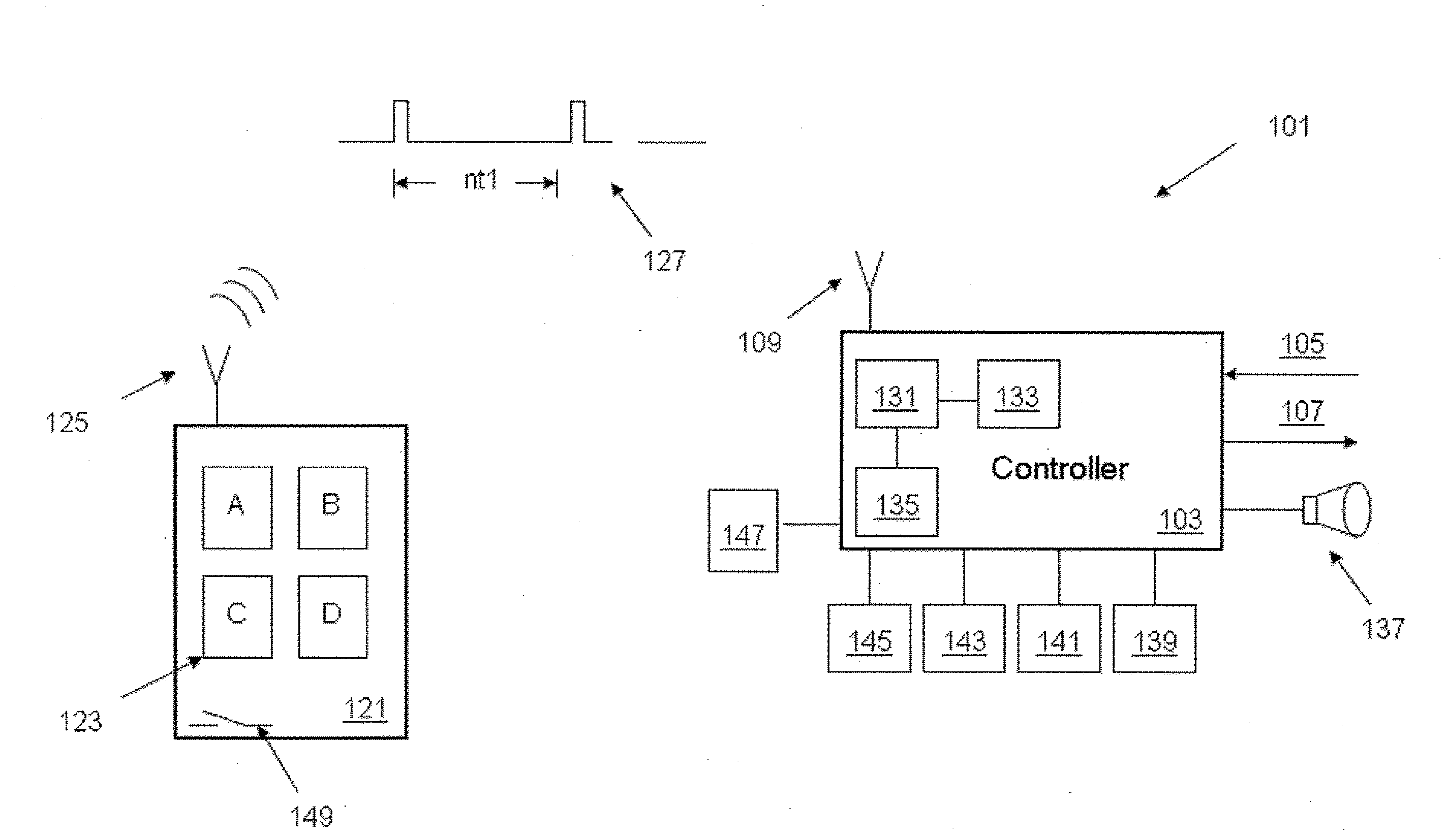
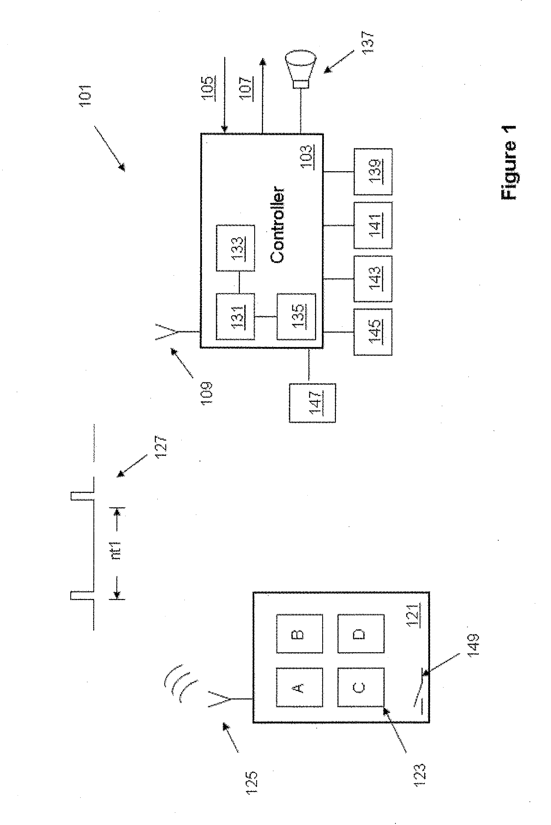
[0015]Shown in FIG. 1, is a representative security and / or vehicle convenience system (hereafter the “system”) 101. System 101 generally comprises one or more authorized transmitters 121 capable of transmitting command signals 127 to a controller 103. A status indicator (not shown) in the form of an audio and / or visual indicator such as an LED, a piezo or equivalent is present in the transmitter 121. One application of the status indicator (not shown) is to let the user know that battery is running low, and that the status has changed from one mode (Passive) to another mode (Active), or from two-way to one-way modes, and that the power source, such as a battery, should be changed or recharged. Such indication could be configured coincident with or at a threshold level preceding the automatic change of modes, which will be discussed in further detail below.

[0016]In response to the signal received from one or more authorized transmitters 121, controller 103 executes commands received ...


PUM


Abstract

A remote control transmitter configured to operate with a vehicle controller. The transmitter is operable in an active mode and a passive mode and/or in the alternative embodiment the transmitter is operable as a one-way or a two-way transmitter. The transmitter is configured to switch from one mode, such as the passive or two-way mode, to the other mode, such as active or one-way mode, in response to at least one of a user activated signal or a battery threshold signal.

Description

CROSS-REFERENCE TO RELATED PATENT APPLICATIONS[0001]This application claims the benefit of and priority to U.S. Non-Provisional patent application Ser. No. 11 / 070,520, entitled PASSIVE TRANSMITTER, filed Mar. 2, 2005, which is herein incorporated by reference. This application is related to U.S. patent application Ser. No. 11 / 247,567, entitled FORCED ARMING, filed Oct. 10, 2005, the disclosure of which is hereby incorporated by reference in its entirety.BACKGROUND[0002]1. Field of the Invention[0003]The present invention relates generally to vehicle security and convenience systems, employing a transmitter that automatically or passively activates some or all of the functions controllable by a vehicle mounted controller programmed to respond to such transmitters.[0004]2. Discussion of the Prior Art[0005]Vehicle security and convenience systems have evolved over time. One of the more significant contributions of these systems is the remote access to the vehicle and the ability to dis...

Claims


Application Information

Patent Timeline
Patent Type & Authority Applications(United States)
IPC IPC(8): G05B19/00
CPCB60R25/24B60R25/406G07C9/00182G07C9/00309G07C2009/00587G08C17/00G08C2201/61
Inventor JONES, MARKMOORE, MARSHALLTALPALATSKY, SAM
Owner MAGNADYNE CORP
Why Eureka
Try Eureka