Light emitting device

a technology of light emitting device and buffer, which is applied in the direction of static indicating device, electroluminescent light source, instruments, etc., can solve the problems of frequent changes in the potential of the source signal line, increased power consumption of the external power source, so as to achieve easy rise in the temperature of the buffer, more power, and variation in luminance

Inactive Publication Date: 2010-01-26
SEMICON ENERGY LAB CO LTD
View PDF13 Cites 1 Cited by
  • Summary
  • Abstract
  • Description
  • Claims
  • Application Information

AI Technical Summary

Benefits of technology

[0020]Further, the current value to a light emitting element of a pixel portion also depends on a temperature. In particular, in the case of using an organic compound for a light emitting element, temperature characteristics are significant. Even when the same voltage is applied between electrodes of an EL element, more current flows through the EL element as the temperature rises because of the temperature characteristics of the EL element. Therefore, a display device consumes more power as the temperature of the EL element rises, which increases luminance of a light emitting element.
[0024]As described above, the light emitting element high power potential (ANODE) changes depending on a deterioration over time, a temperature change, a frequency of use, and the like. Accordingly, the buffer high power potential (VBH) is required to follow the light emitting element high power potential (ANODE) and to be in synchronization with the light emitting element high power potential (ANODE) in order to reduce the power required for charging at the desired light emitting element high power potential (ANODE).
[0026]As a result, a conventional buffer circuit tends to consume more power as described above, which easily rises the temperature of the buffer. In accordance with the generated heat of the buffer, a temperature distribution occurs in a pixel portion, leading to variations in luminance.
[0029]The invention is made in view of the aforementioned problems so that a circuit using an inverter, such as a buffer consumes less power. Further, the invention is made to reduce power consumption required for charging and discharging the source signal line of an active matrix display device using a light emitting element.
[0037]According to the invention, when a high power potential (VBH or ANODE) rises, a low power potential of a buffer rises by following the high power potential. Therefore, a rise in a potential difference between the high power potential and the low power potential supplied to the buffer (inverter) can be suppressed. As a result, data of the source signal line can be rewritten by less power. Accordingly, heat generated by the buffer can be suppressed, which can reduce variations in luminance of the pixel portion caused by the generated heat.

Problems solved by technology

Therefore, when an output of the source signal line often changes, power consumption of the external power source increases.
Accordingly, in the digital gray scale method, power consumption of the external power source increases when displaying an image which requires a large number of gray scale levels such as a natural image and an image in which logic is frequently inversed per one row such as a 1-dot checker (here, light emission pixels and non-light emission pixels are alternately arranged in an active matrix structure), as a potential of the source signal line frequently changes.

Method used


Image

  • Light emitting device
  • Light emitting device
  • Light emitting device

Examples


embodiment mode 1

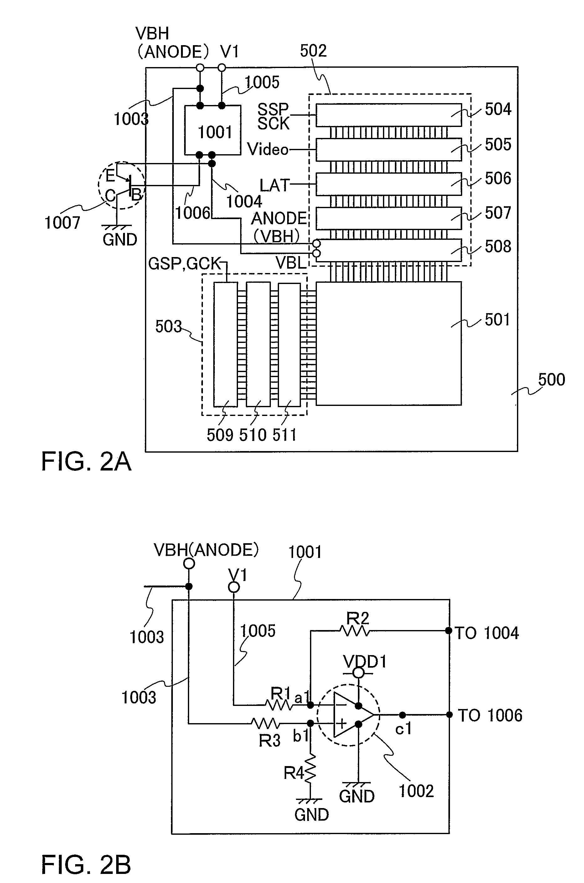
[0051]This embodiment mode is described with reference to FIGS. 1, 2A, and 2B.

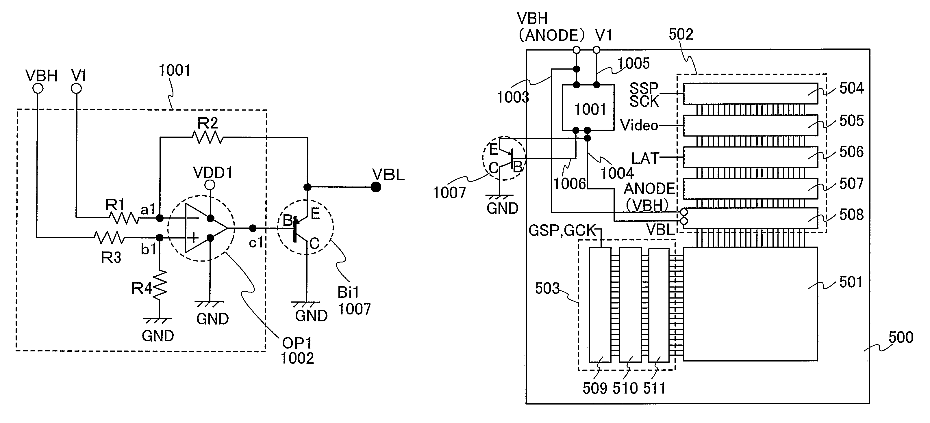
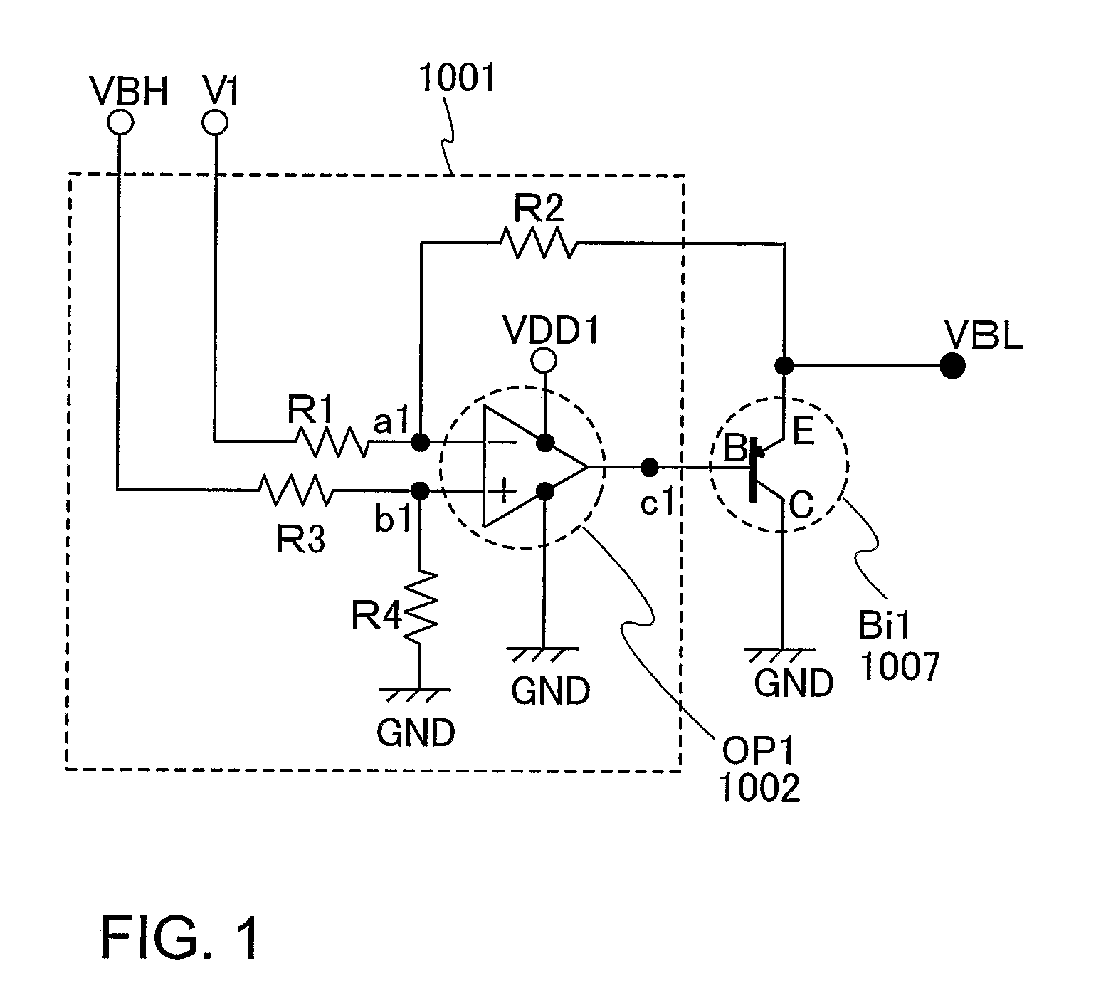
[0052]FIG. 1 is a circuit diagram of a potential generating circuit of this embodiment mode. As shown in FIG. 1, the potential generating circuit includes resistors R1 to R4, an operational amplifier (OP1) 1002, and a bipolar transistor (Bi1) 1007.

[0053]Two power source connecting terminals of the operational amplifier OP1 are inputted with a high power potential (VDD1) and a low power potential (GND) respectively. Further, an output terminal c1 of the operational amplifier (OP1) is connected to a base terminal B of the bipolar transistor (Bi1). The base terminal B of the bipolar transistor (Bi1) is connected to the output terminal c1 of the operational amplifier (OP1) and a collector terminal C thereof is connected to the low power potential (GND).

[0054]The resistor R1 has one terminal connected to a high power potential (V1) and the other terminal connected to an input terminal al of the operational ampl...

embodiment mode 2

[0070]FIG. 3 is a circuit diagram of a potential generating circuit of this embodiment mode. As shown in FIG. 3, the potential generating circuit includes the resistors R1 to R4 and the operational amplifier (OP1).

[0071]Two power source connecting terminals of the operational amplifier (OP1) are inputted with the high power potential (VDD1) and the low power potential (GND) respectively.

[0072]The resistor R1 has one terminal connected to the high power potential (V1) and the other terminal connected to an input terminal al of an operational amplifier (OP1) 1102. The resistor R2 has one terminal connected to the input terminal a1 of the operational amplifier (OP1) 1102 and the other terminal connected to an output terminal c1 of the operational amplifier (OP1) 1102. The resistor R3 has one terminal connected to a high power potential (VBH) and the other terminal connected to an input terminal b1 of the operational amplifier (OP1) 1102. The resistor R4 has one terminal connected to th...

embodiment mode 3

[0085]As described in Embodiment Modes 1 and 2, the invention is preferably applied to an electronic device which is required to have a high resolution display portion as the invention can suppress power consumption of an EL display device and variations in luminance of the display portion caused by the high resolution of the pixels. Examples are a television device (a television, a television receiver), a camera such as a digital camera, and a digital video camera, a portable phone device (a portable phone), a portable information terminal such as a PDA, a portable game machine, a monitor, a computer, an audio reproducing device such as a car audio set, and an image reproducing device provided with a recording medium such as a home game machine. Specific examples of these are described with reference to FIGS. 11A to 11F.

[0086]For example, the invention can be applied to a portable information terminal shown in FIG. 11A, a digital video camera shown in FIG. 11B, a portable phone sho...


PUM


Abstract

Power consumption required for charging and discharging a source signal line is reduced in an active matrix EL display device. A bipolar transistor (Bi1) has a base terminal B connected to an output terminal c1 of an operational amplifier (OP1), a collector terminal C connected to a low power potential (GND), and an emitter terminal E connected to a resistor R2. A high power potential (VBH) is a potential in synchronization with a high power potential of a light emitting element. A potential of the output terminal c1 of the operational amplifier (OP1) is outputted as a buffer low power potential (VBL). The low power potential (VBL) corresponds to a potential difference between the high power potential (VBH) and a high power potential (V1). Accordingly, the low power potential (VBL) can follow the high power potential (VBH), that is a high power potential of the light emitting element.

Description

TECHNICAL FIELD[0001]The invention relates to a light emitting device provided with a light emitting element.BACKGROUND ART[0002]Research on an active matrix light emitting device having a self-luminous element has been becoming more active. A typical example of such a self-luminous device is an EL display device.[0003]In recent years, a flat panel display device which is widely used for a display portion of a portable information terminal as well as for a medium-size or a large-size display device has the increasing number of pixels in accordance with the high resolution. In accordance with the increase in the number of pixels, these displays employ pixels in an active matrix structure which has a thin film transistor (TFT) in each pixel and can store image data.[0004]There are an analog gray scale method and a digital gray scale method in a gray scale method of an active matrix EL display device. The digital gray scale method has a time gray scale method, an area gray scale method...

Claims


Application Information

Patent Timeline
Patent Type & Authority Patents(United States)
IPC IPC(8): G09G5/00
CPCG09G3/3266G09G3/3275G09G3/3233G09G2300/0861G09G2330/021G09G2320/0223G09G2320/0242G09G2320/041G09G2320/043G09G2300/0871G09G3/20G09G3/30G09G3/32H05B33/12
Inventor IWABUCHI, TOMOYUKIMIYAKE, HIROYUKI
Owner SEMICON ENERGY LAB CO LTD
Why Eureka
Try Eureka