Radar device

a technology of a radar and a target angle, applied in the direction of measurement devices, using reradiation, instruments, etc., can solve the problem of not being able to obtain information indicating whether a target angle (defining the front direction as 0 degrees) is positive or negativ

Active Publication Date: 2008-12-18
MITSUBISHI ELECTRIC CORP
View PDF18 Cites 63 Cited by
  • Summary
  • Abstract
  • Description
  • Claims
  • Application Information

AI Technical Summary

Benefits of technology

[0011]The present invention is devised to solve the above-mentioned problem of incompatibility between the ambiguity in sign and the reduction in size and cost, and has an object of providing a radar device allowing a sign of a Doppler frequency or a sign of a target angle to be determined as positive or negative even when only a real signal is obtained as a received signal.

Problems solved by technology

Furthermore, when a DBF-system antenna is used, information indicating whether a target angle (defining the front direction as 0 degree) is positive or negative cannot be obtained.

Method used


Image

  • Radar device
  • Radar device
  • Radar device

Examples


first embodiment

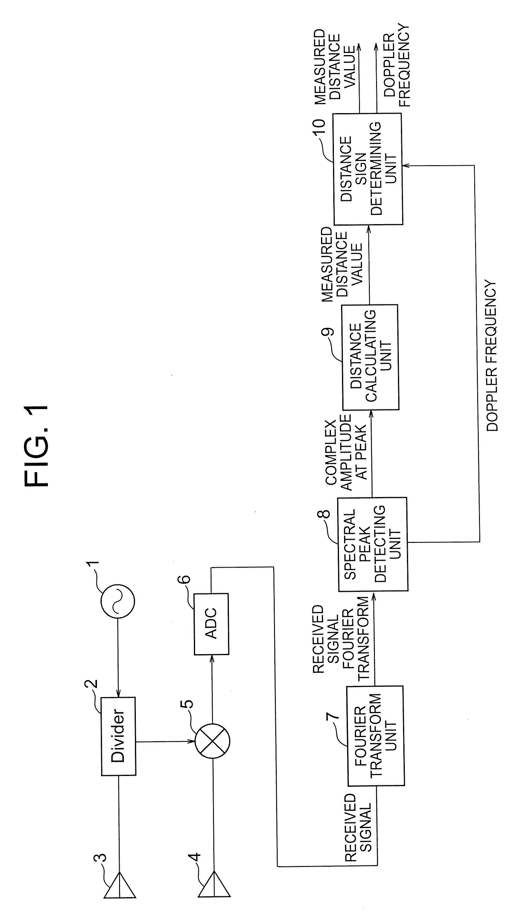
[0026]FIG. 1 is a block diagram illustrating a configuration of a radar device according to a first embodiment of the present invention. The radar device illustrated in FIG. 1 includes an oscillator 1, a divider 2, a transmitting antenna 3, a receiving antenna 4, a receiver 5, and an A / D converter 6. The oscillator 1 generates a transmission wave. The divider 2 divides the transmission wave output from the oscillator 1. One of the transmission waves output from the divider 2 is input to the transmitting antenna 3 which in turn emits the transmission wave into space. The receiving antenna 4 receives a reflected wave generated by the transmission wave reflected by an object present in the space to obtain a received wave. The received wave is input from the receiving antenna 4 to the receiver 5 where the received wave is mixed with the output of the transmission wave input from the divider 2 to generate a received signal. The A / D converter 6 performs analog-to-digital (AD) conversion o...

second embodiment

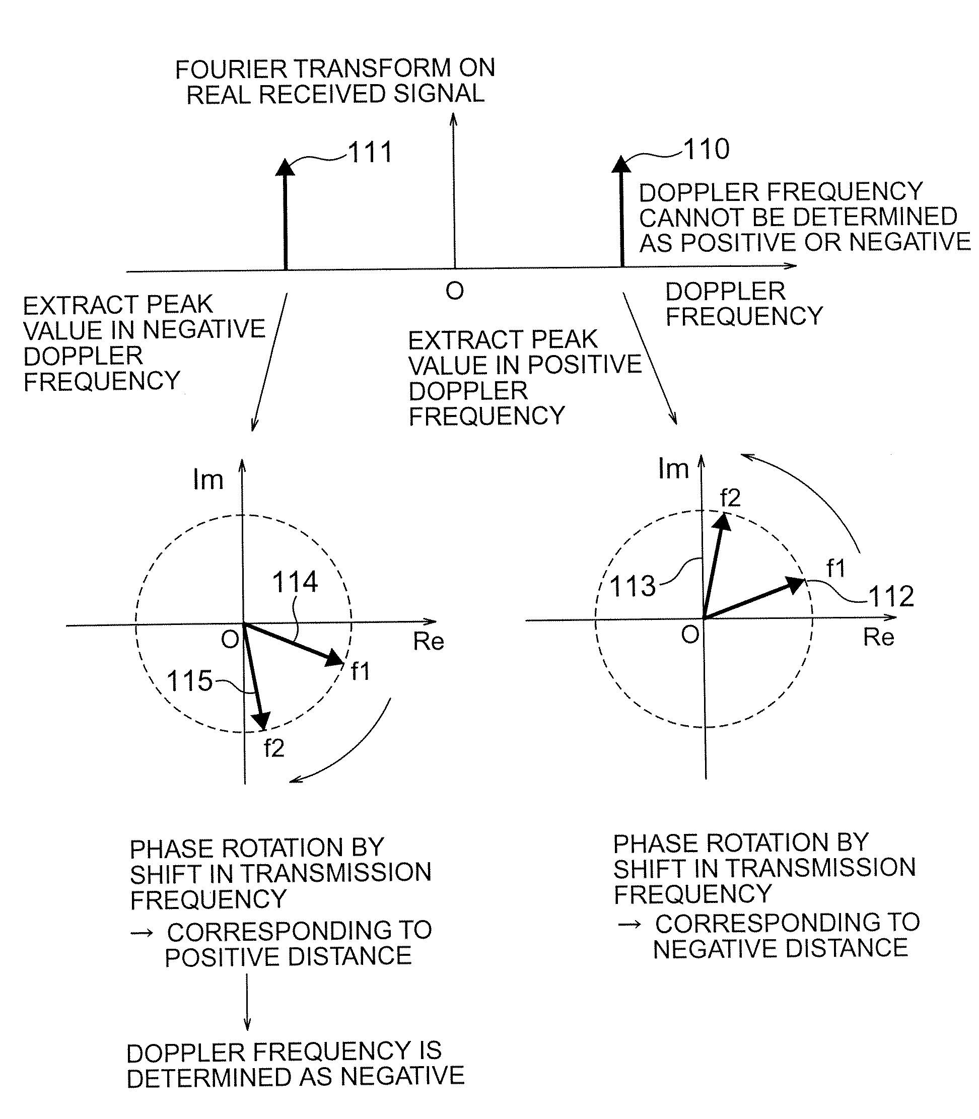
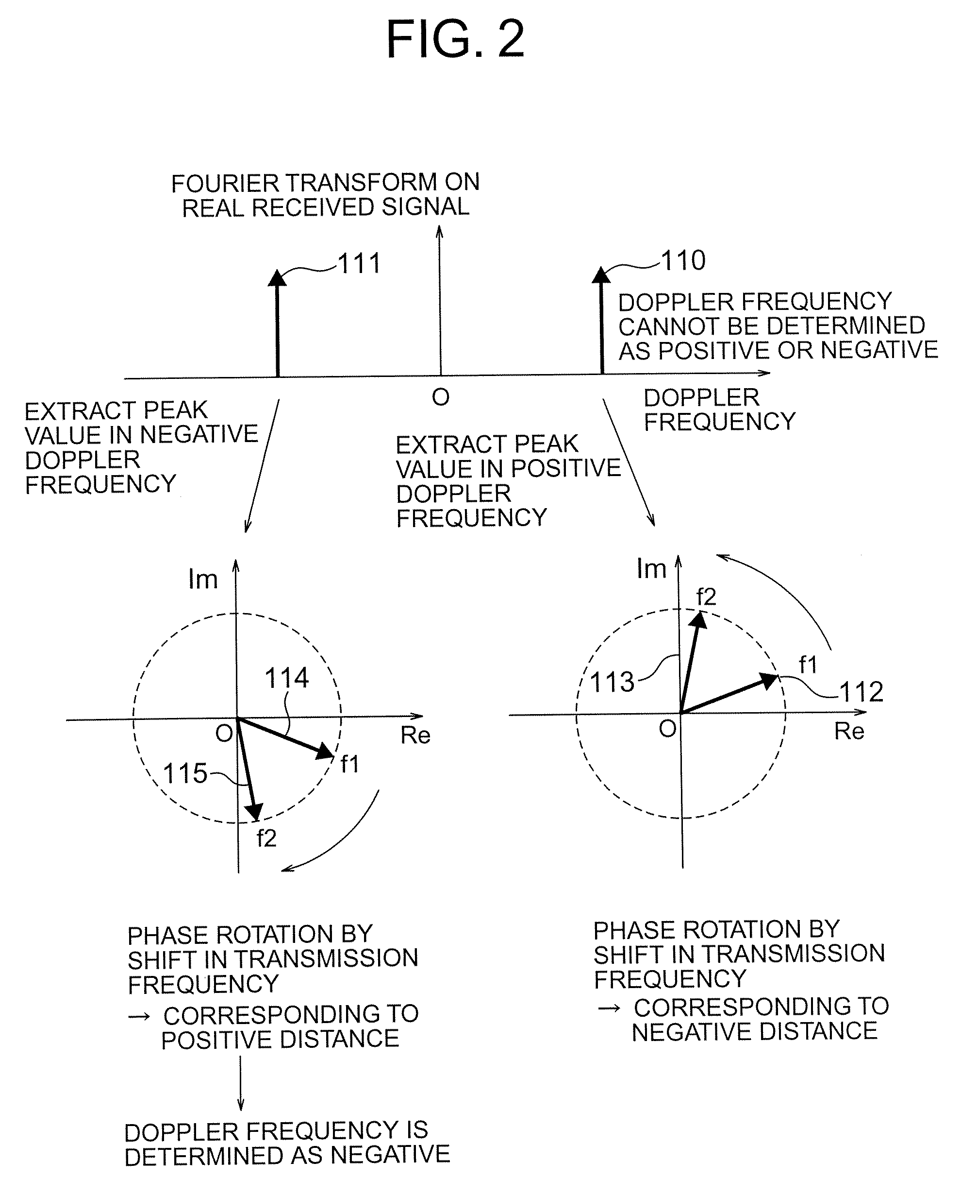
[0057]In the first embodiment described above, the peaks are detected in both the positive Doppler frequency and the negative Doppler frequency. Only when the result of the calculation of a distance is a positive value, the measured distance value and the Doppler frequency are output. This second embodiment discusses a configuration of a radar device for detecting a peak in any of the positive Doppler frequency domain and the negative Doppler frequency domain. Then, based on the result of the sign of the calculated distance, the sign of the Doppler frequency is corrected.

[0058]FIG. 3 is a block diagram illustrating a configuration of a radar device according to the second embodiment of the present invention. In the configuration illustrated in FIG. 3 according to the second embodiment, the same components as those in the first embodiment shown in FIG. 1 are denoted by the same reference numerals, and the description thereof will be omitted. In contrast with the configuration illustr...

third embodiment

[0064]In the first embodiment described above, an example of the configuration of the radar device applicable to the use of a continuous wave as the transmission wave has been described. An embodiment of the radar device, in which the transmission wave is subjected to pulse modulation, will now be described.

[0065]FIG. 5 is a block diagram illustrating a configuration of a radar device according to the third embodiment of the present invention. In the configuration illustrated in FIG. 5 according to the third embodiment, the same components as those of the configuration illustrated in FIG. 1 according to the first embodiment are denoted by the same reference numerals, and the description thereof will be omitted. In contrast with the configuration illustrated in FIG. 1 according to the first embodiment, the third embodiment illustrated in FIG. 5 further includes a pulse modulating unit 101, a distance selecting unit 102, and a distance range determining unit 103 serving as the distanc...


PUM


Abstract

A radar device includes: an oscillator for generating a wave at a plurality of transmission frequencies; a transmitting antenna; a receiving antenna; a receiver for generating a real received signal; a Fourier transform unit for performing a Fourier transform on the real received signal in a time direction; a spectral peak detecting unit for receiving an input of a result of the Fourier transform to extract peak complex signal values of Doppler frequency points having a maximum amplitude; a distance calculating unit for storing the peak complex signal values and for calculating a distance to a reflecting object based on the stored peak complex signal values to output the obtained distance as a measured distance value; and a distance sign determining unit for determining validity of the measured distance value and for outputting the measured distance value and the Doppler frequency according to a result of determination.

Description

BACKGROUND OF THE INVENTION[0001]1. Field of the Invention[0002]The present invention relates to a radar device for emitting a wave into space, receiving the wave reflected by an object present in the space, and for performing signal processing on the received wave to measure the object.[0003]2. Description of the Related Art[0004]Generally, a radar emits an electromagnetic wave into space and receives the electromagnetic wave reflected by a target present in the space to know the presence / absence of the target, specifically, to detect the target. When the target moves relative to the radar, the measurement of a frequency shift caused by the Doppler effect, specifically, the measurement of a Doppler frequency also allows measurement of a relative velocity of the target, specifically, a Doppler velocity.[0005]For the measurement of the Doppler frequency, an I / Q detection system for obtaining two orthogonal signal components as received signals is generally used. According to this det...

Claims


Application Information

Patent Timeline
Patent Type & Authority Applications(United States)
IPC IPC(8): G01S13/08
CPCG01S7/292G01S2007/356G01S13/52G01S7/354G01S7/356
Inventor WAKAYAMA, TOSHIOINABA, TAKAYUKIMURAYAMA, SATORUSEKIGUCHI, TAKASHI
Owner MITSUBISHI ELECTRIC CORP
Why Eureka
Try Eureka