DC-DC converter with temperature compensation circuit

a technology of temperature compensation and converter, which is applied in the direction of process control, television system, instruments, etc., can solve the problems of insufficient known circuit of the conventional dc-dc converter in view of the requirements for high precision, inability to effectively counteract the influence of the liquid crystal display panel, and inability to realize the temperature compensation operation of positive temperature coefficient or negative temperature coefficien

Inactive Publication Date: 2008-12-18
VASTVIEW TECH
View PDF3 Cites 43 Cited by
  • Summary
  • Abstract
  • Description
  • Claims
  • Application Information

AI Technical Summary

Benefits of technology

This patent describes an improved design for a device called a DC-DC converter which helps control the power output from a battery or other source of electricity. By combining different parts into one system, this new version of the converter works better when exposed to varying temperatures. This makes it easier to keep electronic devices running smoothly no matter what kind of weather they're facing.

Problems solved by technology

The technical problem addressed in this patent text is the inadequacy of conventional DC-DC converters in terms of precision, durability, and stability, especially in liquid crystal displays. The conventional arrangement of the DC-DC converter is not precise in regulating the output voltage, and the conventional temperature compensation techniques mentioned in previous patent references are not practical for high precision applications. The patent text proposes a solution to overcome these issues by providing a new DC-DC converter circuit that is more precise, durable, and stable.

Method used


Image

  • DC-DC converter with temperature compensation circuit
  • DC-DC converter with temperature compensation circuit
  • DC-DC converter with temperature compensation circuit

Examples


Embodiment Construction

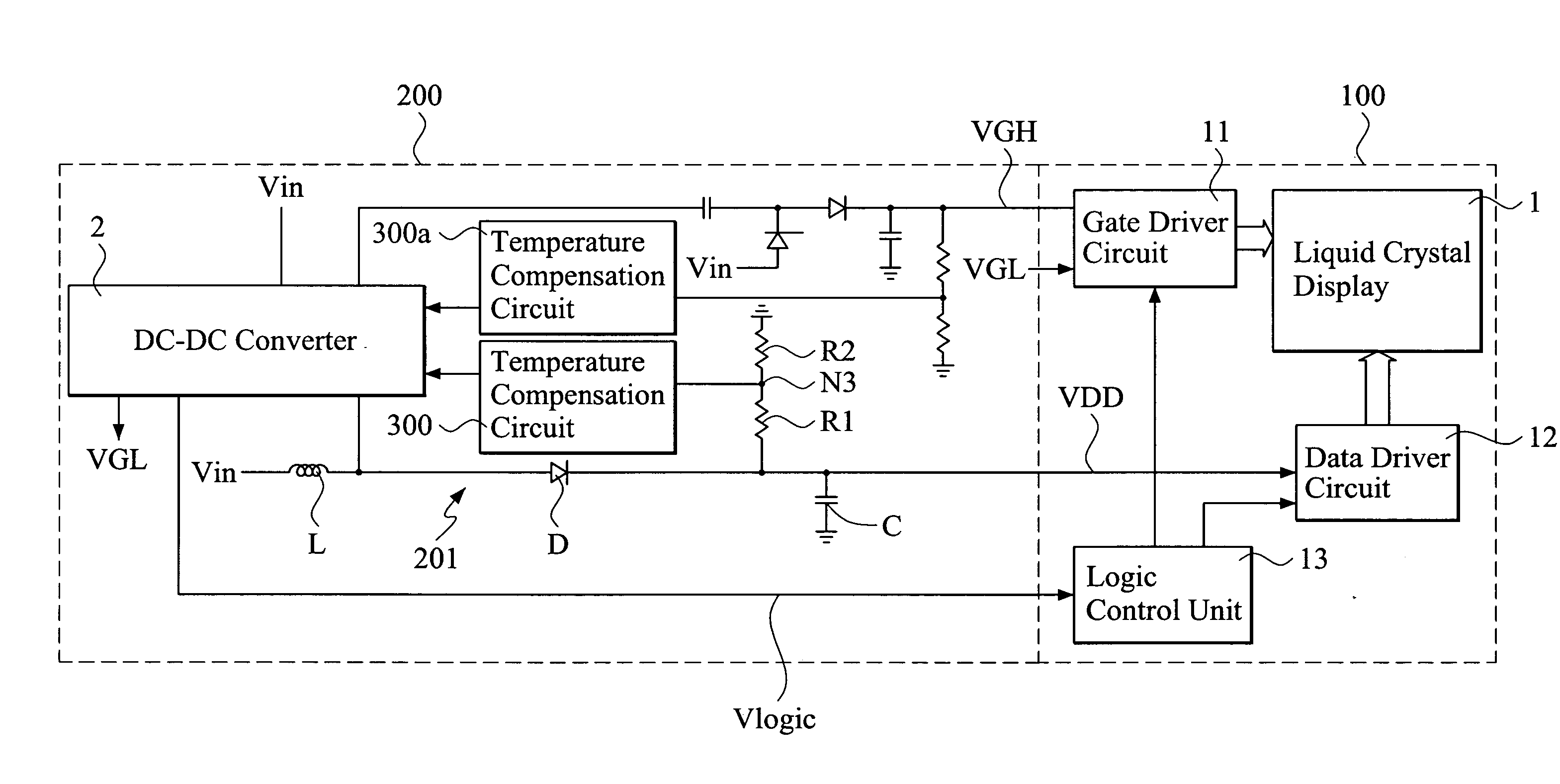
[0030]With reference to the drawings and in particular to FIG. 3, a circuit diagram of a DC-DC converter constructed in accordance with the present invention is shown. To simplify the description and to provide a cross reference and comparison between the DC-DC converter of the present invention and a conventional converter, parts / devices / elements used in the DC-DC converter of the present invention that are the same as those counterparts of the conventional converter will bear the same references as discussed previously in the BACKGROUND section. It is also noted that a DC-DC converter configured for providing a data driving voltage of a liquid crystal display is taken as an example for explanation of the present invention in the following description.

[0031]The DC-DC converter in accordance with the present invention, generally designated with reference numeral 2a, comprises a transistor based switching unit 21 having a drain terminal connected to a node N1 between an inductor elem...


PUM


Abstract

A DC-DC converter includes a temperature compensation circuit arranged between a feedback differential amplification circuit and an output voltage detection circuit to compensate the variation of the voltage level of the DC output voltage of the converter caused by ambient temperature changes. The temperature compensation circuit includes a temperature detection circuit that detects the ambient temperature and, in response thereto, generates a temperature signal; and a current source circuit that is connected between a feedback signal input terminal of the feedback differential amplification circuit and the output voltage detection circuit. The current source circuit, based on the temperature signal, generates an electrical current and a compensation voltage proportional to the electrical current. The compensation voltage is applied to the DC output voltage to thereby regulate the voltage level of the DC output voltage. The temperature signal is a temperature signal of positive temperature characteristics and/or a temperature signal of negative temperature characteristics.

Description


Claims


Application Information

Patent Timeline
Owner VASTVIEW TECH
Why Eureka
Try Eureka