System and method for content-based alternate imaging

a content-based alternate imaging and imaging system technology, applied in the field of content-based alternate imaging system and method, can solve the problems of job integrity issues, affecting the quality of content-based alternate imaging, and the approach, which has notable limitations and problems, and achieves the effect of preserving job integrity and facilitating consistent rip settings and resources

Inactive Publication Date: 2008-12-18
XEROX CORP
View PDF21 Cites 8 Cited by
  • Summary
  • Abstract
  • Description
  • Claims
  • Application Information

AI Technical Summary

Benefits of technology

[0003]Methods and systems are provided for content-based alternate imaging in which a single DFE image path includes a raster image processor instance coupled to multiple imaging components (imagers). The DFE may include a plurality of RIP instances, each being operatively coupled with corresponding imagers. The imagers are individually associated with corresponding print engines having different capabilities, such as a color imager providing color page images for consumption by a color print engine, and a monochrome imager creating monochrome images for a monochrome print engine. The present disclosure thus associates a single RIP instance with multiple imagers, and may advantageously provide a content separation component, such as a software module or other logic that controls the operation of the multiple image

Problems solved by technology

This approach, however, has notable limitations and problems.
Conventional splitter software, moreover, is typically limited to use with only one type of pdl file (e.g., PDF files).
These RIP instances do not share internal state information and may therefore lead to job integrity issues.
Furthermore, this technique does not take into account i

Method used


Image

  • System and method for content-based alternate imaging
  • System and method for content-based alternate imaging
  • System and method for content-based alternate imaging

Examples


Embodiment Construction

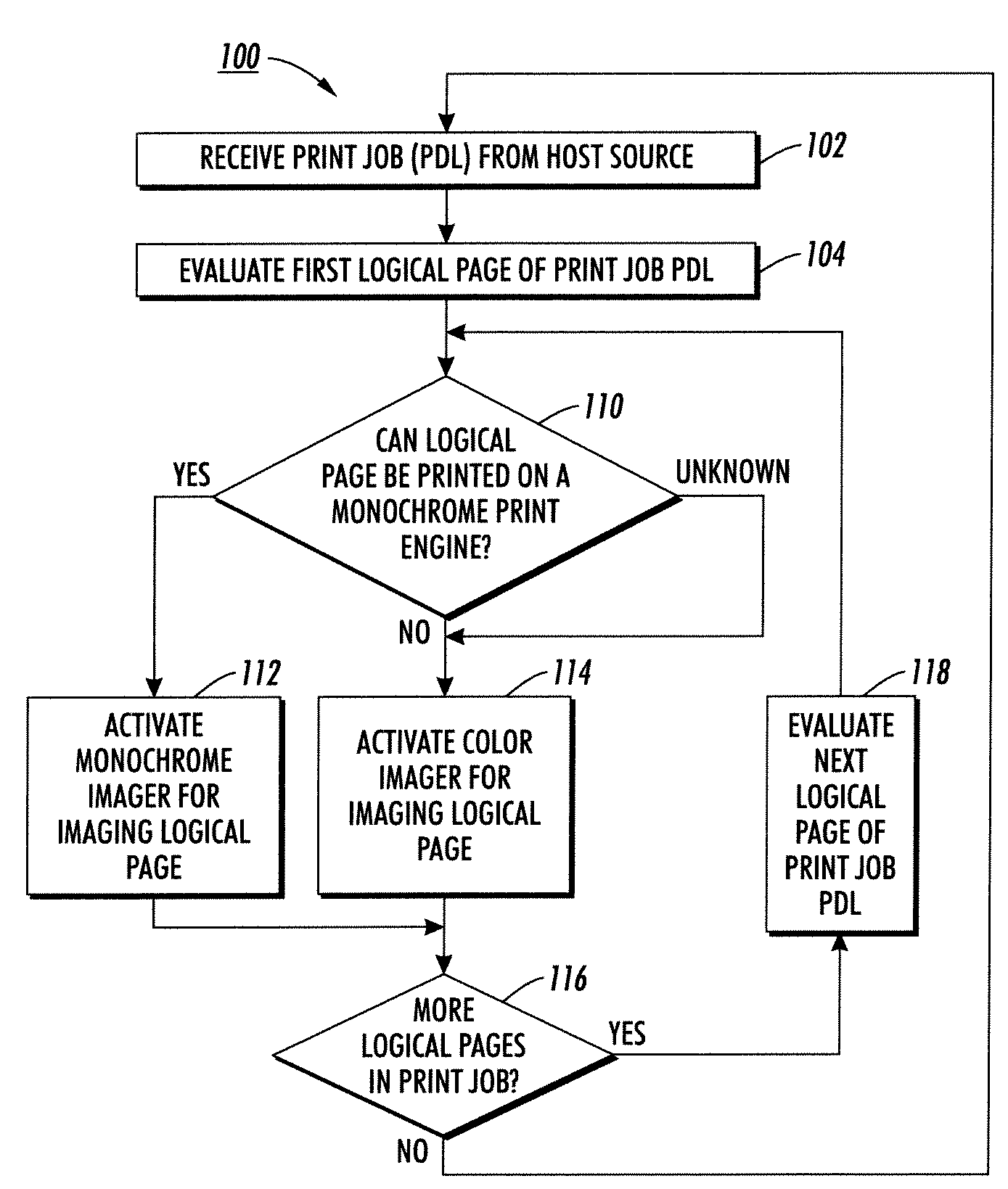
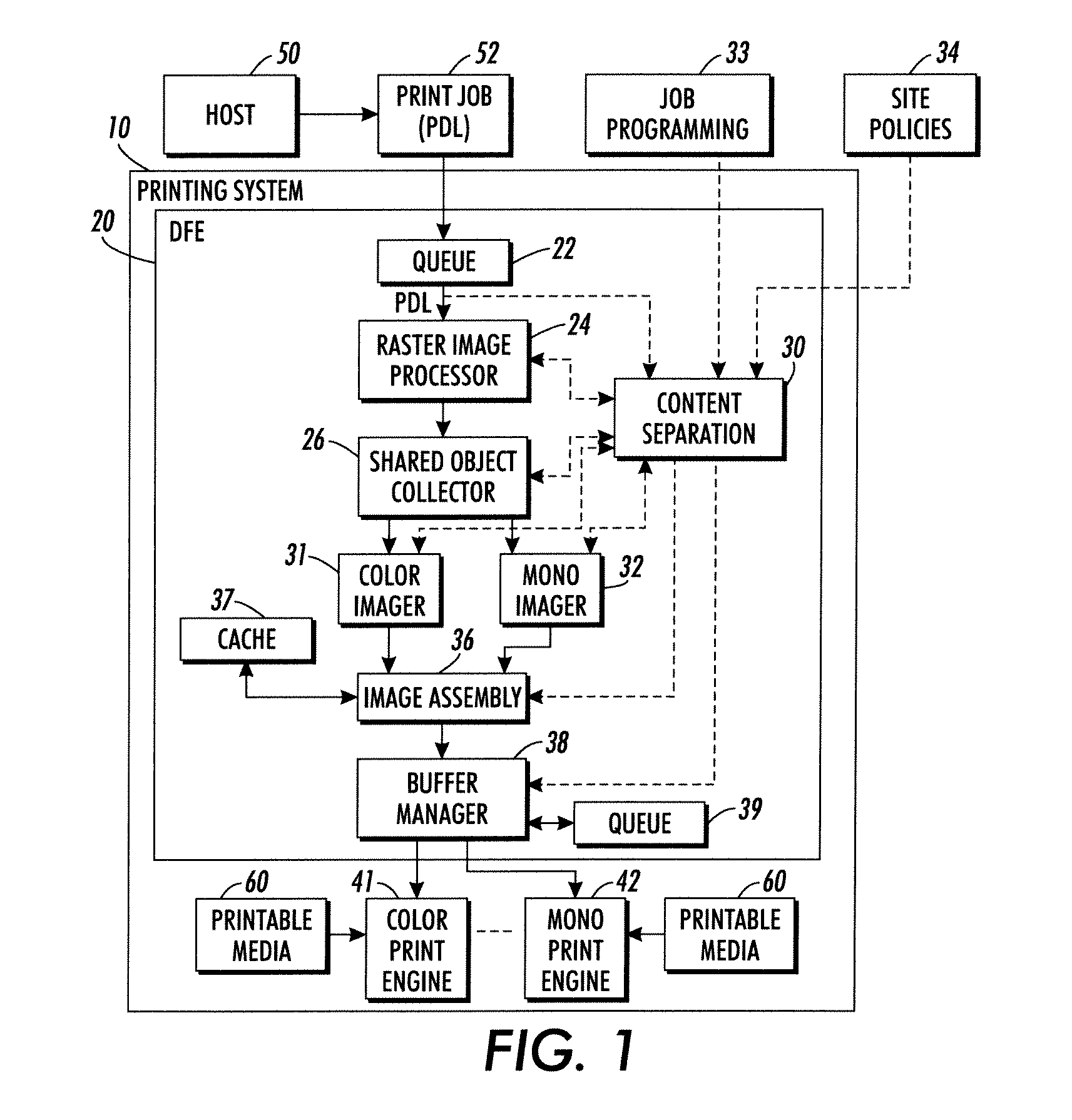
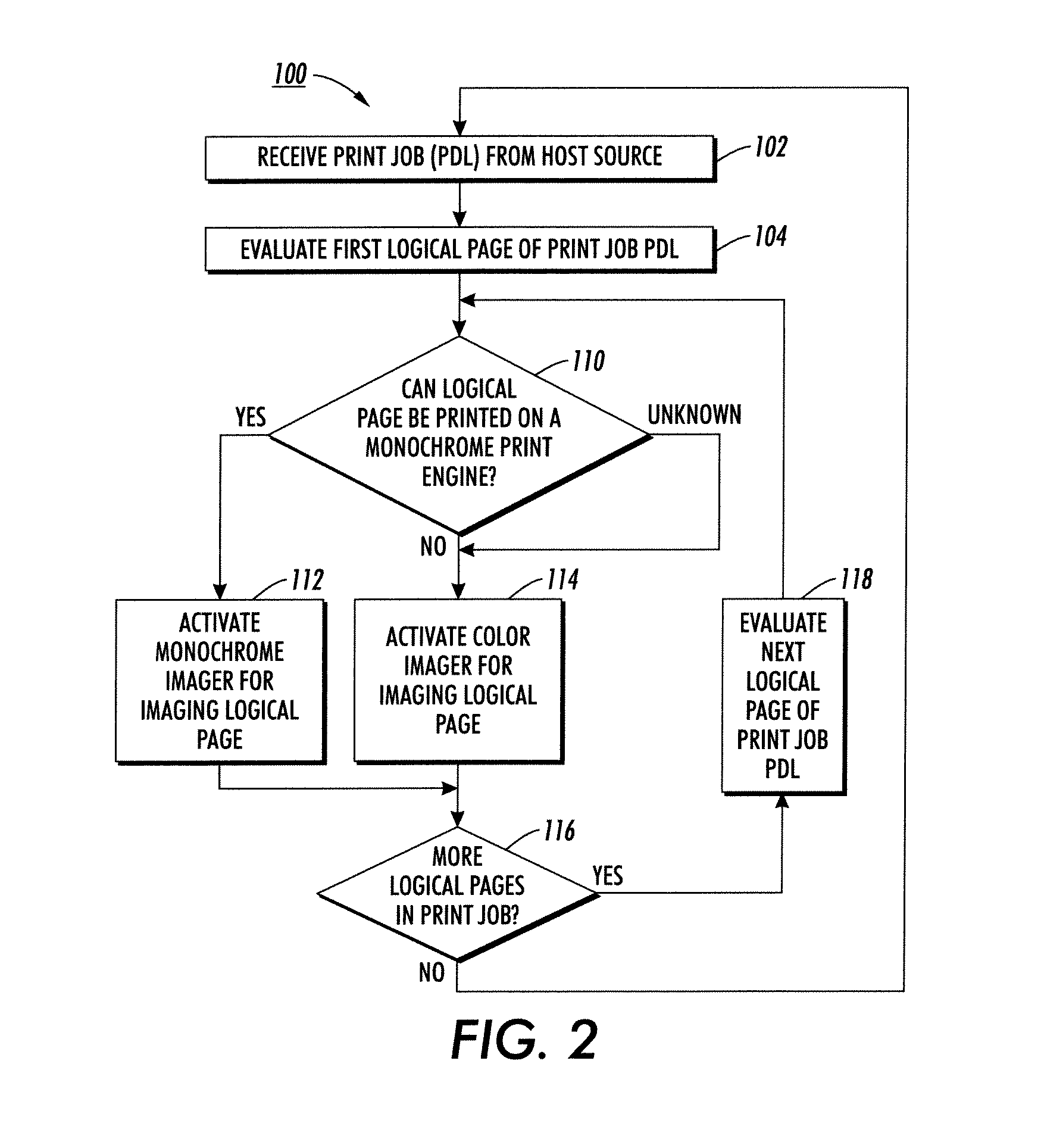
[0010]Referring now to the drawings, FIG. 1 illustrates a printing system 10 in accordance with one or more aspects of the present disclosure, comprising a digital front end (DFE) 20 with a single raster image processor instance 24 and a plurality of imagers 31, 32 operatively associated with corresponding print engines 41, 42 that print images on a printable media 60 introduced thereto. The DFE 20 may include additional RIP instances (not shown), such as a PostScript RIP, and PCL RIP, etc., wherein each RIP instance is operatively coupled with corresponding multiple imagers. Furthermore, a single print job may be processed by two or more RIP instances of the same type (e.g., page parallel RIP). The print engines 41, 42 may all be under the control of a common control system for printing images from a common print job stream, although not a requirement of the disclosure. In the example of FIG. 1 two imagers 31 and 32 are provided in the DFE 20 corresponding to a color print engine 4...


PUM


Abstract

Printing systems and methods are presented for front end processing of an incoming print job in a printing system, in which a single raster image processor instance creates ripped objects from incoming page description language files and one of two or more imagers is selectively activated according to incoming print job logical page content to create raster page images for ripped objects associated with a given logical page of the incoming print job. The imager selection can be made according to cost considerations and color printing capabilities to economize the usage of a higher cost print engine associated with a first imager while ensuring that the imager is associated with a print engine having the capabilities required for the content of the given logical page. In this manner, individual logical pages can be imaged in a single digital front end by a monochrome imager if possible, and other logical pages are imaged by a color imager where needed or where the color requirements cannot be discerned by evaluating the incoming job content. The selection of the imager can also be based on other factors, such as job programming associated with the incoming print job, site policies, image assembly considerations, and sheet ordering considerations.

Description

BACKGROUND[0001]Commercial printing systems generally include a digital front end (DFE) that processes incoming print jobs in the form of page description language (PDL) files to create print-ready images, as well as a print engine that receives the images and prints these onto paper or other printable media. Currently, it is cheaper and faster to print a monochrome sheet on a monochrome print engine than it is to print that same monochrome sheet on a color print engine. It is therefore sometimes desirable to direct monochrome sheets from a given job to a monochrome print system with color sheets being sent to a different color system. In one example, current practice includes splitting an incoming job into two page description language files, such as PDFs, one for mono printing, one for color printing. Each of the PDFs is then treated is a separate print job and processed by separate RIPping and imaging components of two different DFEs. The separation of the incoming print job is c...

Claims


Application Information

Patent Timeline
IPC IPC(8): G06F15/00
CPCG06F3/1219G06F3/1248
Inventor SMITH, MARK A.
Owner XEROX CORP
Why Eureka
Try Eureka