Imaging apparatus

a technology of imaging equipment and dust removal, which is applied in the field of imaging equipment, can solve the problems of not being able to always say that dust is removed efficiently, and the operation takes considerable time, and achieve the effect of efficiently removing dust adhesion to the imaging device subuni

Inactive Publication Date: 2008-12-18
SONY CORP
View PDF2 Cites 3 Cited by
  • Summary
  • Abstract
  • Description
  • Claims
  • Application Information

AI Technical Summary

Benefits of technology

[0012]According to this embodiment of the invention, when dust adhering to the imaging device subunit is shaken off by moving the imaging device subunit using the first and second actuators which act to move the imaging device subunit in the first direction and in the second direction substantially perpendicular to the fir...

Problems solved by technology

Therefore, it cannot be always said that dust is removed efficiently.
Consequently, in order to remove dust sufficiently, the...

Method used


Image

  • Imaging apparatus
  • Imaging apparatus
  • Imaging apparatus

Examples


first embodiment

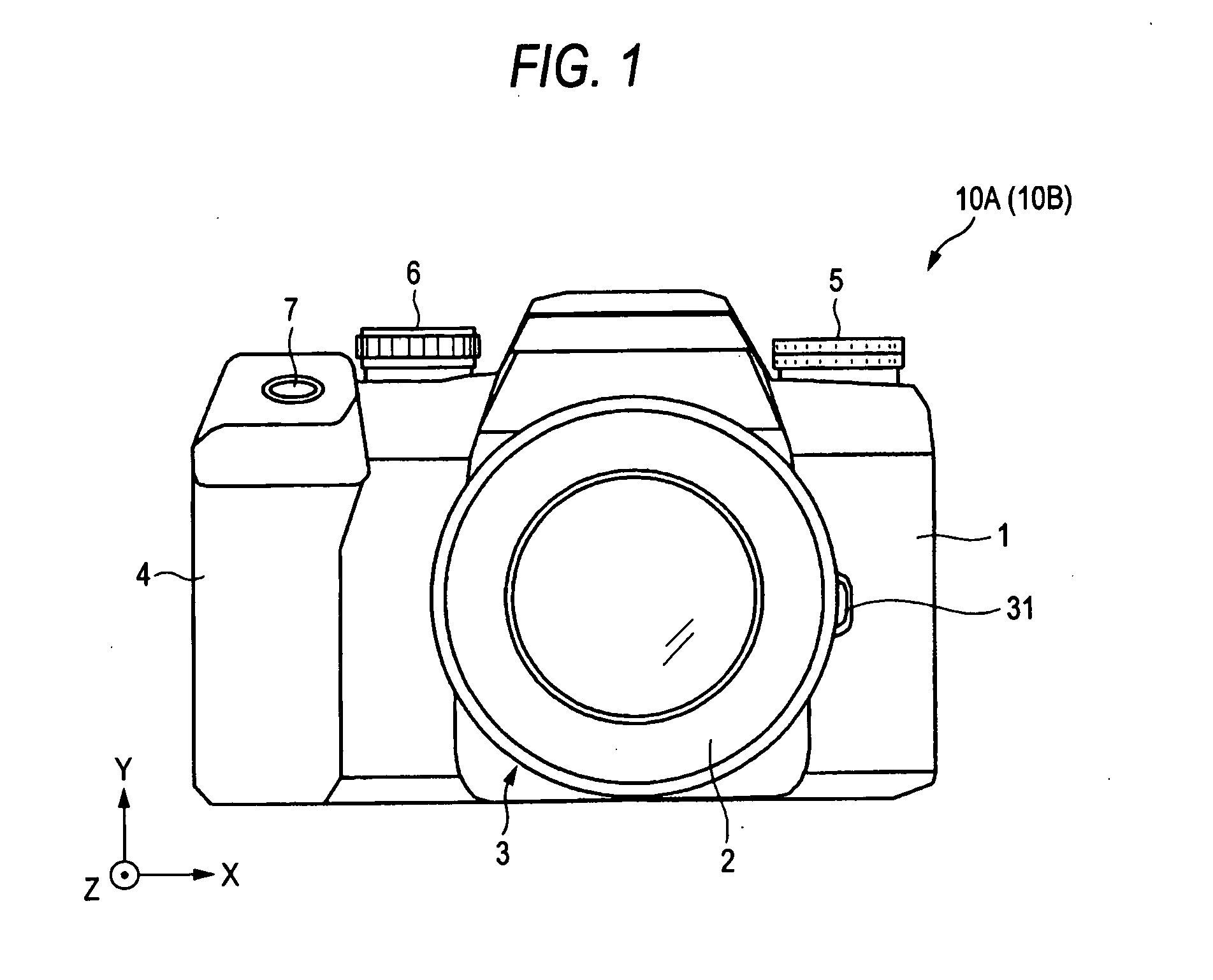
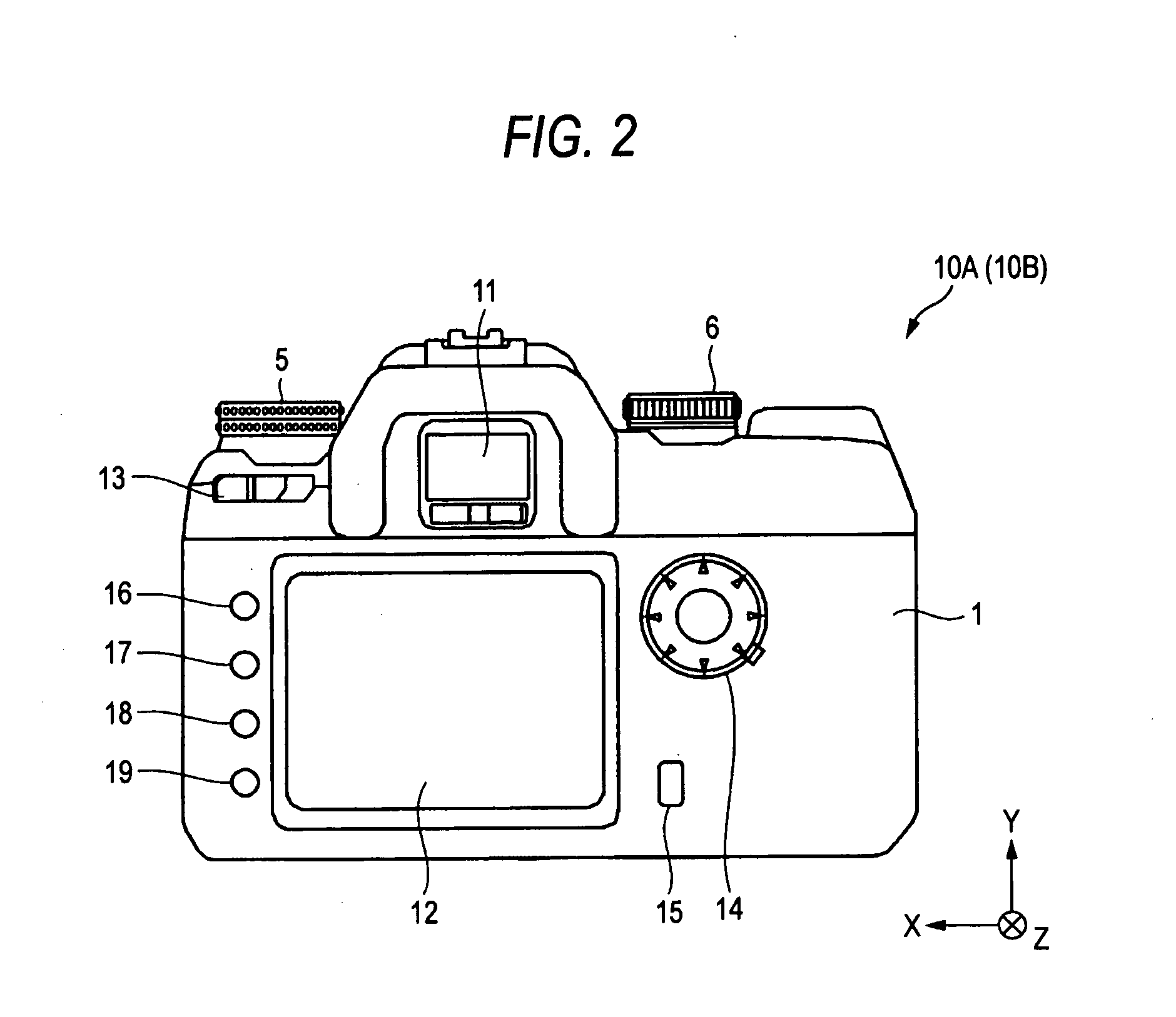
[0029]FIGS. 1 and 2 show the outside appearance of an imaging apparatus 10A associated with a first embodiment of the present invention. FIG. 1 shows the outside appearance of the front side of the imaging apparatus 10A. FIG. 2 shows the outside appearance of the rear side of the imaging apparatus 10A. As shown in FIG. 1, the imaging apparatus 10A is configured as a digital single-reflex still camera including a camera body 1 and a taking lens assembly 2 (replaceable lens) detachably mounted to a substantially front central portion of the camera body 1.

[0030]In FIG. 1, the camera body 1 has a lens mount 3 in a front and almost central portion of the body, a grip portion 4 protruding from the front left end of the body, a control value-setting dial 5 mounted in a front, right, upper part of the body for setting a control value, a mode-setting dial 6 mounted in a front, left, upper part of the body to permit the user to switch the shooting mode, and a shutter release button 7 mounted ...

second embodiment

[0093]An imaging apparatus 10B associated with a second embodiment of the present invention is similar in structure with the imaging apparatus 10A according to the first embodiment described already in connection with FIGS. 1-6 except for the structure of the gravity detection-sensing portion.

[0094]Specifically, the gravity direction-sensing portion 313B of the imaging apparatus 10B is configured to detect the direction of gravity, based on information about the velocity at which the imaging device subunit Uc is moved. Detection of the direction of gravity by the gravity direction-sensing portion 313B is described in the following.

313B>

[0095]FIGS. 14A-14C and 15 illustrate the principle on which the direction of gravity is detected by the gravity direction-sensing portion 313B. In each of FIGS. 14A-14C, a piezoelectric actuator 9 similar in structure with the actuator shown in FIG. 8 is shown. The drive shaft 91 is in a posture where the shaft extends in the vertical direction. A ch...

modified embodiment

[0125]It is not essential that the imaging device subunit Uc according to the above-described embodiments be equipped with the low-pass filter 108. The low-pass filter (optical filter) may be omitted. Furthermore, instead of the low-pass filter 108, a simple glass member having no filtering function may be mounted.


PUM


Abstract

There is disclosed an imaging apparatus having: (a) a drive mechanism for moving an imaging device subunit having an imaging device in mutually perpendicular first and second directions; (b) a first actuator for moving the imaging device subunit in the first direction; (c) a second actuator for moving the imaging device subunit in the second direction; (d) a sensing device for detecting the direction of gravity; and (e) a dust-removing device for shaking off dust adhering to the imaging device subunit by moving the subunit using at least one of the two actuators. The dust-removing device has: a setting unit for setting a direction of motion in which the imaging device subunit is moved, based on the direction of gravity detected by the sensing device; and a selecting unit for selecting an actuator used to drive the imaging device subunit in the direction of motion set by the setting unit from the first and second actuators.

Description

CROSS REFERENCE TO RELATED APPLICATION[0001]The present invention contains subject matter related to Japanese Patent Application JP 2007-157565 filed in the Japanese Patent Office on Jun. 14, 2007, the entire contents of which being incorporated herein by reference.BACKGROUND OF THE INVENTION[0002]1. Field of the Invention[0003]The present invention relates to an imaging apparatus capable of permitting an imaging device subunit having an imaging device therein to be moved in a given direction.[0004]2. Description of the Related Art[0005]Some imaging apparatuses designed as digital cameras are equipped with a shake correction mechanism that shifts the position of an imaging device subunit having an imaging device and a low-pass filter (optical filter) therein to achieve anti-jitter stabilization during shooting (see, for example, JP-A-2006-78898 (patent reference 1)).[0006]Meanwhile, in an imaging apparatus such as a digital single-lens reflex camera, dust may intrude into the body o...

Claims


Application Information

Patent Timeline
IPC IPC(8): G02B27/64B08B7/02
CPCG02B27/646G03B5/00G03B11/00G03B17/02G03B2217/002H04N5/2253H04N23/54
Inventor TANAKA, YOSHIHARU
Owner SONY CORP
Why Eureka
Try Eureka