
Error control apparatus

a control apparatus and error technology, applied in the field of interconnection devices, can solve the problems of inability to execute subsequent operations, affecting the operation of the crossbar module, so as to achieve the effect of reducing the scop

Inactive Publication Date: 2008-12-18
FUJITSU LTD
View PDF28 Cites 2 Cited by
  • Summary
  • Abstract
  • Description
  • Claims
  • Application Information

AI Technical Summary

Benefits of technology

The present invention aims to minimize the impact of errors in an information processing system that has multiple information processing modules. The invention provides an error control apparatus that detects errors in input packets and generates completion data to replace the data unit containing the error. Additionally, the invention includes a holding unit for temporarily holding input packets and an output unit for outputting a packet only when no error is detected in all areas of the input packet. These features help to prevent errors from spreading and minimize the impact on the overall system performance.

Problems solved by technology

However, many of the conventional crossbar modules do not have a function of handling error packets.
Accordingly, there is a probability that the influence of error packets extends to the circuit elements and / or other information processing modules in the crossbar module so that the subsequent operations can not be executed.
However, in this configuration, the error packet itself is transferred without being discarded, and the influence of the error may extend to a wider area.
Also, there is a probability that another error packet may be sent out before the operation of the information processing module that has sent out the first error packet is halted.
However, in the conventional technique, there is a probability that the influence of error packets extend over partitions so that the entire server system (or many of the circuit elements in the server system) has to be halted.
In such a case, the stable operation of the server system is inhibited for a long time period.

Method used


Image

  • Error control apparatus
  • Error control apparatus
  • Error control apparatus

Examples


Embodiment Construction

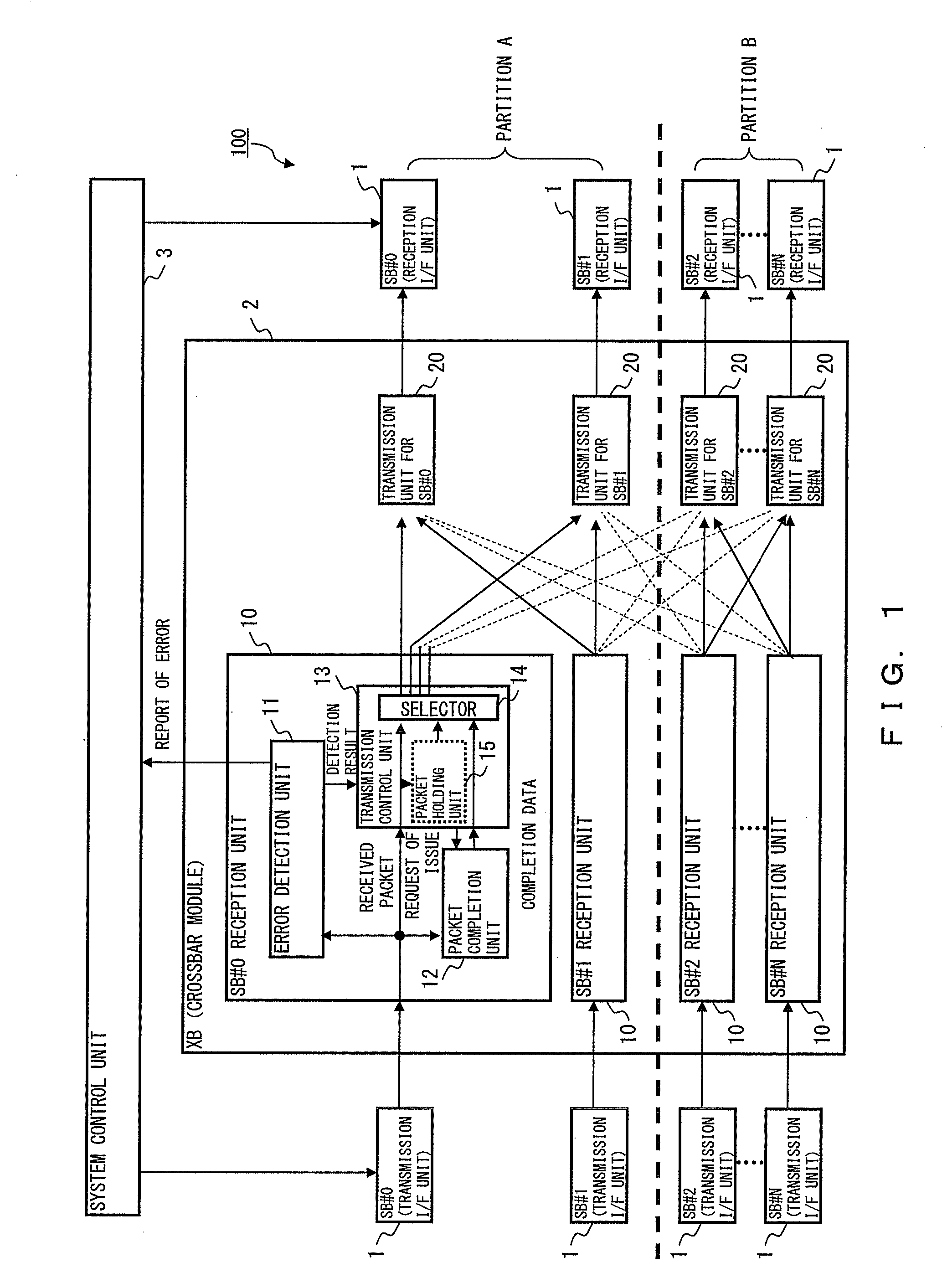
[0017]FIG. 1 shows a configuration of an information processing device having an error control apparatus according to an embodiment. In the explanations below, a server system 100 that executes information processing corresponding to requests received from a client (not shown) is used as an example of the information processing device.

[0018]The server system 100 includes a plurality of system board modules (SB) 1, a crossbar module (XB) 2, and a system control unit 3.

[0019]Each of the system board modules 1 is an information processing module that includes a CPU, a memory device, a transmission I / F unit, and a reception I / F unit. In this example, the server system 100 includes “N+1” system board modules (#0 through #N). Also, in FIG. 1, the CPUs and the memory devices are not shown in order to clarify the illustration, and only the transmission I / F unit and the reception I / F unit in each system board module 1 are shown. Each system board module 1 can transmit a packet to one or a pl...


PUM


Abstract

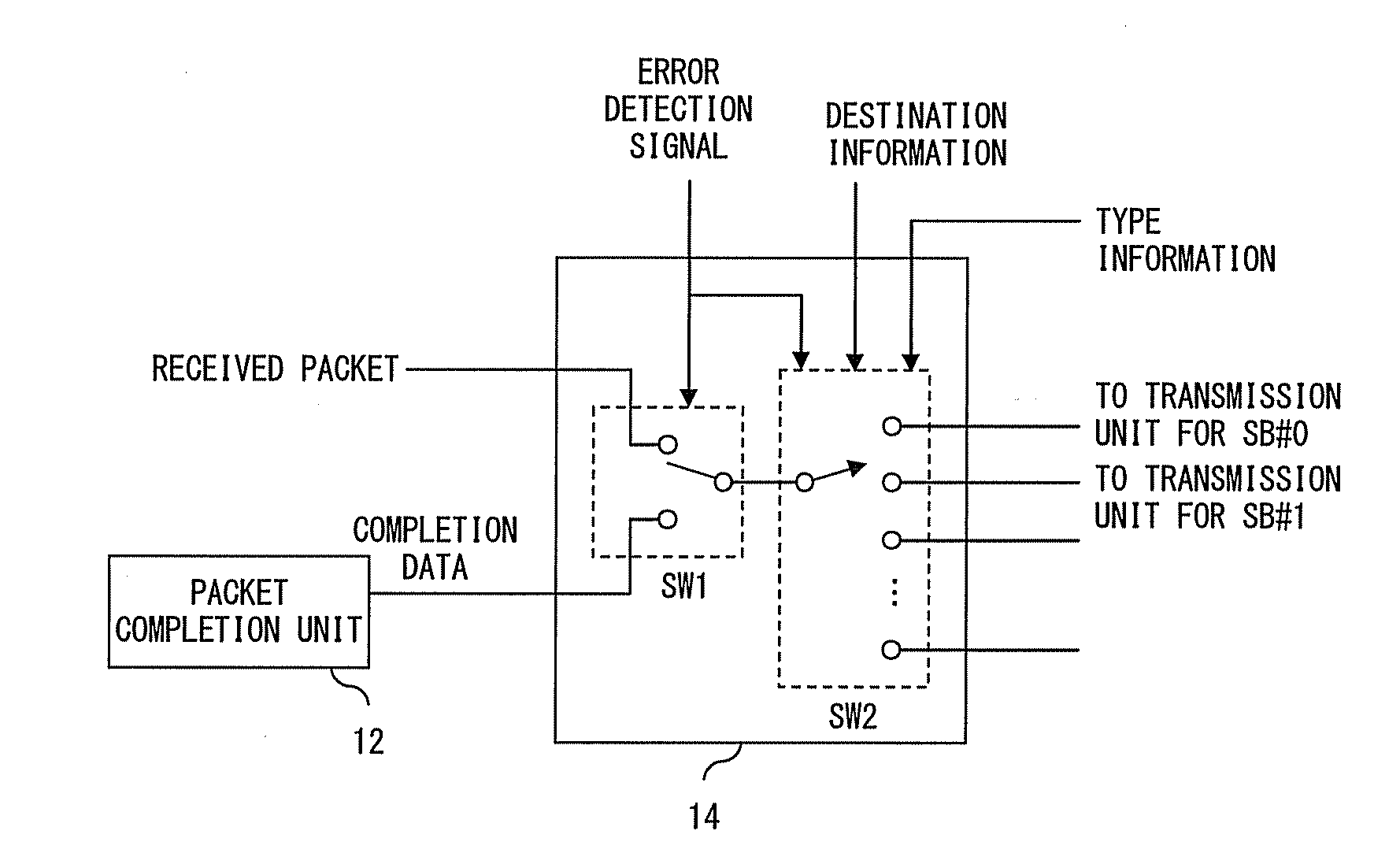
A plurality of system board modules are connected to a crossbar module. An error detection unit detects an error in a packet received from a corresponding system board module. When an error is detected by the error detection unit, a transmission control unit issues a completion data generation request. When receiving the completion data generation request, a packet completion unit generates completion data. When receiving an error packet, a selector circuit outputs a completion packet in which completion data is provided in place of a data unit involving error.

Description

CROSS REFERENCE TO THE RELATED APPLICATION[0001]This is a continuation of a PCT application PCT / JP2006 / 303451, which was filed on Feb. 24, 2006.BACKGROUND OF THE INVENTION[0002]1. Field of the Invention[0003]The present invention relates to an interconnection device for interconnecting a plurality of information processing modules, and may be applied to a error control apparatus for controlling errors detected in the interconnection device.[0004]2. Description of the Related Art[0005]A configuration in which a large scale saver system is realized by interconnecting a plurality of information processing modules is known as a conventional technique. In such a configuration, each of the information processing modules has a CPU and a memory device, and can perform information processing corresponding to given programs. Also, it is possible to expand the server system by increasing the number of the information processing modules to be interconnected.[0006]A plurality of the information ...

Claims


Application Information

Patent Timeline
Patent Type & Authority Applications(United States)
IPC IPC(8): H04L1/24
CPCG06F11/10H04L1/0045H04L1/0072H04L2001/0097G06F11/08G06F11/30G06F9/06
Inventor MURAKAMI, HIROSHIKUSANO, YOSHIHIROSUGIZAKI, GOUNAKAGAWA, SATOSHI
Owner FUJITSU LTD
Learn More