Radio transmitting apparatus and radio receiving apparatus

a radio transmitting and receiving apparatus technology, applied in the direction of receiver monitoring, digital transmission, secret communication, etc., can solve the problems of large amount of arithmetic operations required to calculate calibration coefficients, difficult to reduce the size of difficult to install the radio transmitting and receiving apparatus. achieve the effect of performing a highly accurate calibration process for each subcarrier, preventing an increase in hardware size and power consumption

Inactive Publication Date: 2008-12-18
NEC CORP
View PDF1 Cites 22 Cited by
  • Summary
  • Abstract
  • Description
  • Claims
  • Application Information

AI Technical Summary

Benefits of technology

[0023]It is an object of the present invention to provide a radio transmitting apparatus and a radio receiving apparatus which are capable of perfor

Problems solved by technology

However, since RF circuits of a radio transmitting and receiving system are analog circuits and analog signals are sent between the radio transmitting and receiving apparatus and the antenna elements, it is not easy to equalize the amplitude characteristics and phase characteristics of the antenna elements.
However, the above radio transmitting and receiving apparatus of the related art is problematic in that since discrete Fourier transform is required for calculating calibration coefficients, the amount of arithmetic operation required to calculate calibration coefficients is large.
Therefore, the hardware scale of the radio transmit

Method used


Image

  • Radio transmitting apparatus and radio receiving apparatus
  • Radio transmitting apparatus and radio receiving apparatus
  • Radio transmitting apparatus and radio receiving apparatus

Examples


first exemplary embodiment

[0053]A radio transmitting and receiving system according to a first exemplary embodiment of the present invention will be described below with reference to the drawings.

[0054]The radio transmitting and receiving system according to the first exemplary embodiment serves as a radio transmitting apparatus (multicarrier transmitting apparatus) having B antenna elements (B represents a positive number).

[0055]As shown in FIG. 3, the radio transmitting apparatus according to the first exemplary embodiment comprises calibration coefficient multipliers 11-1 through 11-B, calibration reference signal generators 12-1 through 12-B, subcarrier modulators 13-1 through 13-B, radio transmitters 14-1 through 14-B, antenna elements 15-1 through 15-B, radio receiver 21, calibration coefficient measurer 22, and calibration controller 23.

[0056]Calibration coefficient multipliers 11-1 through 11-B multiply transmission baseband signals from branches #1 through #B which have been modulated and multiplied...

second exemplary embodiment

[0092]A radio transmitting and receiving system according to a second exemplary embodiment of the present invention will be described below with reference to the drawings.

[0093]The radio transmitting and receiving system according to the second exemplary embodiment serves as a radio receiving apparatus (multicarrier receiving apparatus) having B antenna elements (B represents a positive number).

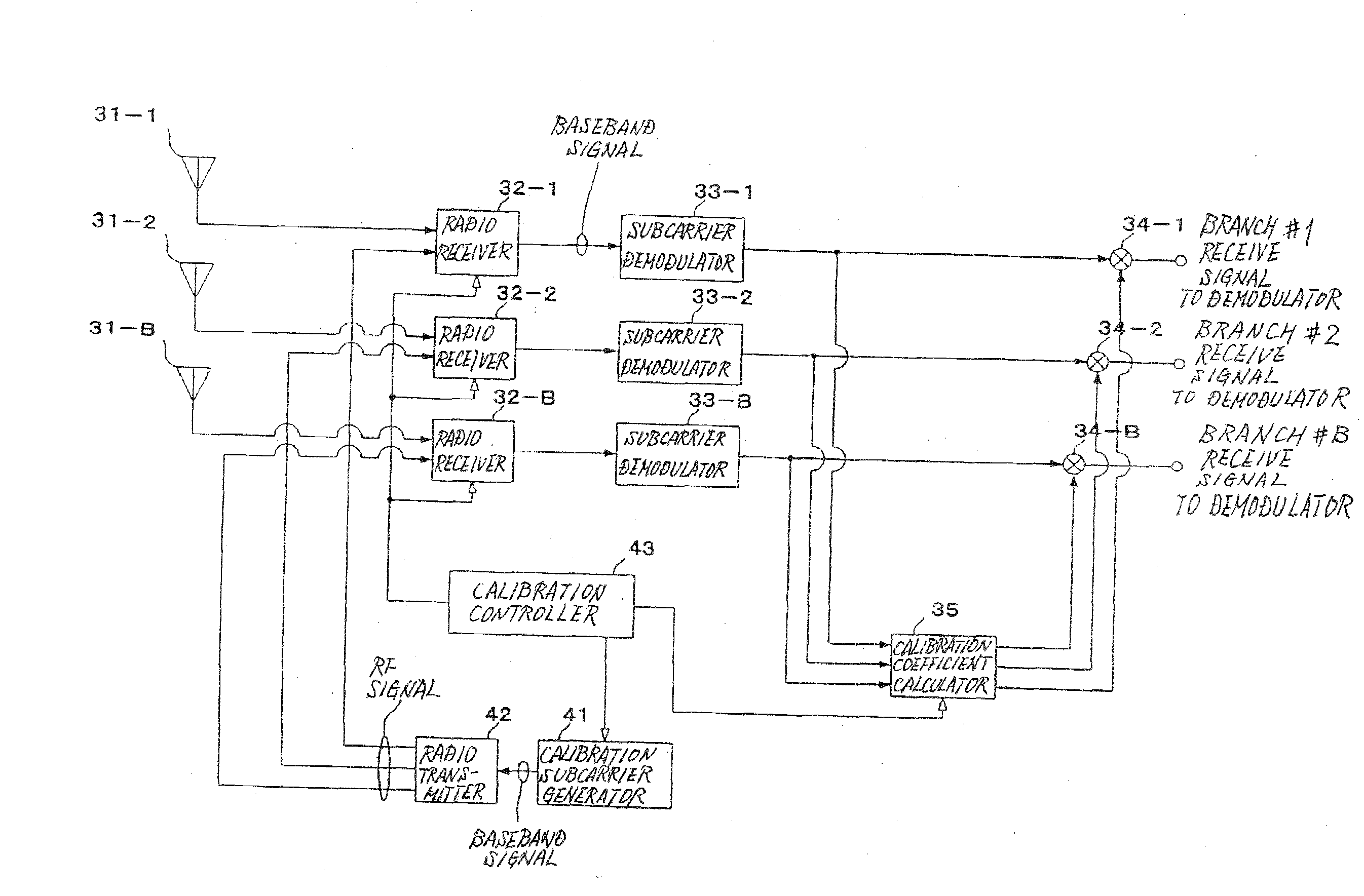
[0094]As shown in FIG. 8, the radio receiving apparatus according to the second exemplary embodiment comprises antenna elements 31-1 through 31-B, radio receivers 32-1 through 32-B, subcarrier demodulators 33-1 through 33-B, calibration coefficient multipliers 34-1 through 34-B, calibration coefficient calculator 35, calibration subcarrier generator 41, radio transmitter 42, and calibration controller 43.

[0095]In a normal mode, radio receivers 32-1 through 32-B receive RF signals from antenna elements 31-1 through 31-B. In a calibration mode, radio receivers 32-1 through 32-B receive RF signa...

embodiment

[0121]An embodiment of a radio transmitting and receiving system according to the present invention will be described below.

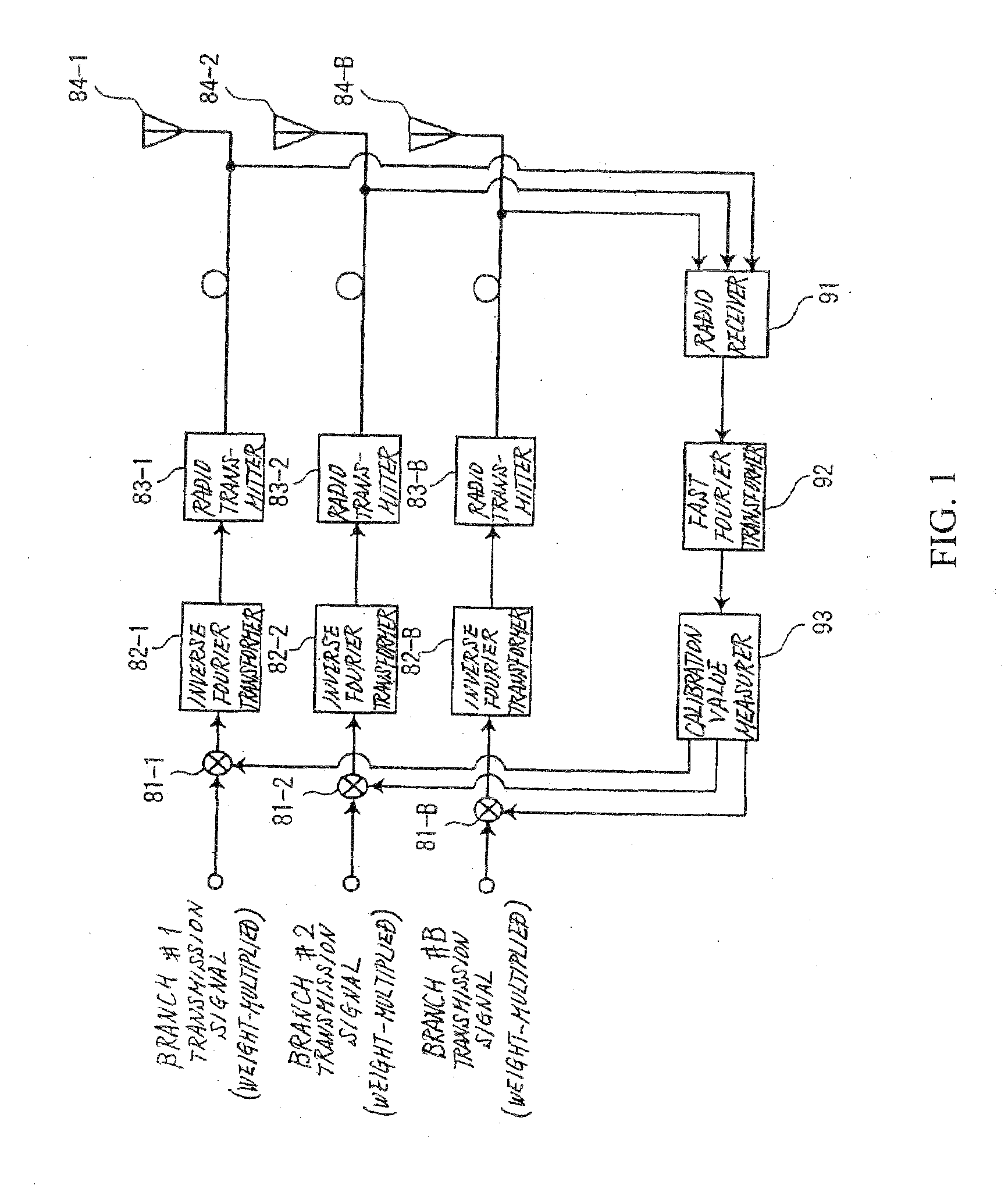
[0122]According to the present embodiment, a subcarrier modulator includes three branches for performing inverse fast Fourier transform (IFFT) in the operation of the radio transmitting apparatus according to the first exemplary embodiment.

[0123]As shown in FIG. 13, the radio transmitting apparatus according to the present embodiment comprises calibration coefficient multipliers 51-1 through 51-3, calibration reference signal generators 52-1 through 52-3, IFFT processors 53-1 through 53-3, radio transmitters 54-1 through 54-3, antenna elements 55-1 through 55-3, radio receiver 61, calibration coefficient measurer 62, and calibration controller 63.

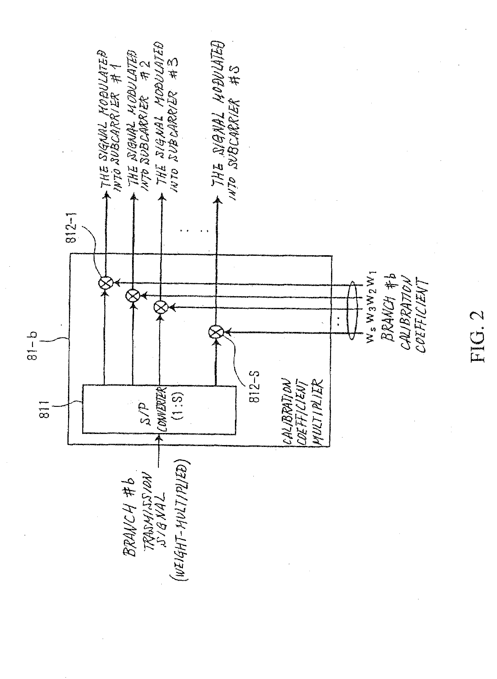
[0124]Calibration coefficient multipliers 51-1 through 51-3 complex-multiply I components and Q components of transmission baseband signals from branches #1 through #3 which have been modulated and multiplied by weight...


PUM


Abstract

A radio transmitting apparatus includes a calibration reference signal generator for generating a calibration reference signal for each of the subcarriers to be calibrated, a subcarrier modulator for modulating the calibration reference signal with the subcarrier, a radio transmitter for frequency-converting a baseband signal, which is the modulated signal, into a transmission signal in a radio frequency band, a radio receiver for frequency-converting the transmission signal in the radio frequency band supplied from the radio transmitter, into a baseband signal, a calibration coefficient measurer for calculating a calibration coefficient from the baseband signal output from the radio receiver, and a calibration coefficient multiplier for multiplying a transmission signal for each of the subcarriers and each of the antenna elements, by the calculated calibration coefficient.

Description

[0001]This application is based upon and claims the benefit of priority from Japanese patent application No. 2006-225249, filed on Aug. 22, 2006, the disclosure of which is incorporated herein in its entirety by reference.BACKGROUND OF THE INVENTION[0002]1. Field of the Invention[0003]The present invention relates to a radio transmitting apparatus and a radio receiving apparatus which employ array antenna technology.[0004]2. Description of the Related Art[0005]Array antenna is a technology for performing radio communications using a plurality of antenna elements. According to array antenna technology, the antenna elements are appropriately weighted to electrically control the directivity of the array antenna into a desired direction for thereby reducing interference between paths or users. It is also known according to array antenna technology to improve reception characteristics by giving phase rotation to a plurality of transmission antenna elements.[0006]For an array antenna to o...

Claims


Application Information

Patent Timeline
IPC IPC(8): H04L27/28
CPCH04L25/03343H04L27/2602H04B17/21H04L27/2653H04L27/2637
Inventor FUTATSUGI, YASUNORI
Owner NEC CORP
Why Eureka
Try Eureka