Moving picture compression coding apparatus

a compression coding and moving picture technology, applied in the field of compression coding apparatus for moving picture data, can solve the problems of difficult to use an encoding parameter suited for the characteristics of an image, heavy load, and increased power consumption

Inactive Publication Date: 2008-12-18
CANON KK
View PDF8 Cites 15 Cited by
  • Summary
  • Abstract
  • Description
  • Claims
  • Application Information

AI Technical Summary

Benefits of technology

[0009]The present invention provides a technique for making degradation in image quality in a boundary portion of regions into which a screen is divided and encoded less noticeable using a simple structure and for providing the capability of setting an encoding parameter suited for the characteristics of an image.

Problems solved by technology

If an encoding circuit operates with significantly high speed to perform the above-described high-speed processing, a problem exists in which the load becomes heavy and power consumption is increased.
Therefore, a predetermined set value is undesirably determined as the encoding parameter for each of the regions, so it is difficult to use an encoding parameter suited for the characteristics of an image.

Method used


Image

  • Moving picture compression coding apparatus
  • Moving picture compression coding apparatus
  • Moving picture compression coding apparatus

Examples


first embodiment

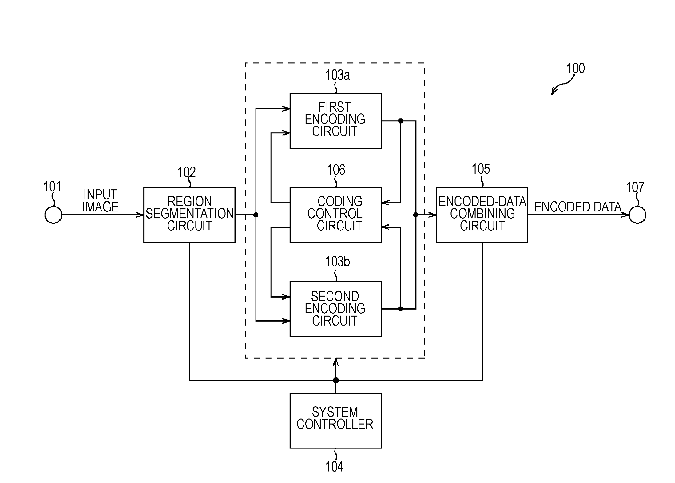
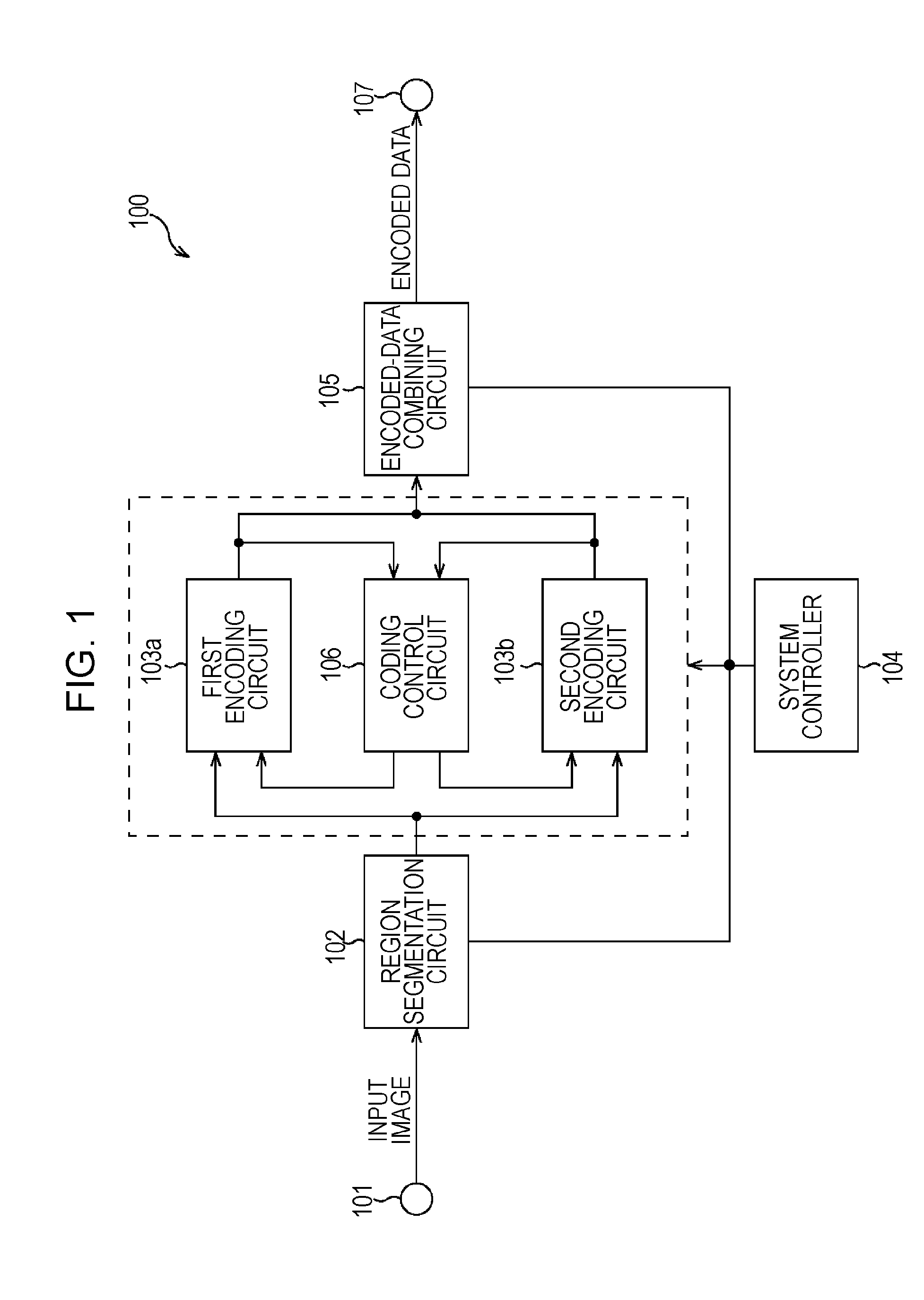
[0022]FIG. 1 is a block diagram that illustrates a structure of a moving picture coding apparatus according to a first embodiment of the present invention. The moving picture coding apparatus in the present embodiment performs compression coding on moving picture data using motion compensation prediction. The moving picture coding apparatus in the present embodiment is applicable to an image pickup device, such as a digital video camera.

[0023]In FIG. 1, the moving picture coding apparatus 100 includes an image signal input terminal 101 configured to receive moving picture data (image signal) input from, for example, an image pickup unit (not shown). The moving picture coding apparatus 100 also includes a region segmentation circuit 102 configured to divide a one-field or one-frame image signal in a moving picture into n regions, a first encoding circuit 103a, and a second encoding circuit 103b. The first and second encoding circuits 103a and 103b each perform encoding using motion c...

second embodiment

[0049]FIG. 6 is a block diagram that illustrates a structure of the moving picture coding apparatus according to a second embodiment of the present invention. The moving picture coding apparatus in the present embodiment performs compression coding on moving picture data using motion compensation prediction, as in the case of the first embodiment. The moving picture coding apparatus in the present embodiment is also applicable to an image pickup device, such as a digital video camera.

[0050]In FIG. 6, the moving picture coding apparatus 600 includes a region segmentation circuit 602, in place of the region segmentation circuit 102 included in the moving picture coding apparatus 100 illustrated in FIG. 1, and further includes a frame memory 601. Of the components illustrated in FIG. 6, the components having the same reference numerals as those of the components illustrated in FIG. 1 are substantially the same as in FIG. 1, so the description thereof is omitted here.

[0051]Operation of ...


PUM


Abstract

A moving picture compression coding apparatus divides a screen into at least three regions and performs compression coding for the at least three regions by encoding units. The moving picture compression coding apparatus includes a coding control unit configured to control the encoding units to encode the data for different regions in parallel and to control the encoding such that the data for an upper region out of two adjacent upper and lower regions in the vicinity of the center of the screen of the at least three regions is encoded prior to the encoding of the data for the lower region or such that the data for a left region of two adjacent left and right regions in the vicinity of the center of the screen of the at least three regions is encoded prior to the encoding of the data for the right region.

Description

BACKGROUND OF THE INVENTION[0001]1. Field of the Invention[0002]The present invention relates to a compression coding apparatus for moving picture data, and in particular, to a technique suited for use in dividing a screen and encoding the moving picture data of the divided screen in parallel by use of a plurality of encoding units.[0003]2. Description of the Related Art[0004]Digital video cameras are well known as a moving picture recording apparatus that has an integrated camera and that obtains an image of a subject, performs compression coding on the obtained moving picture data, and records the moving image data. Instead of traditional magnetic tape, a randomly accessible highly convenient disk medium or semiconductor memory is becoming used in a recent digital video camera. However, in general, disk media have a small amount of memory capacity, so it is necessary to perform compression coding with a high degree of efficiency.[0005]These days, with the expectations for high ima...

Claims


Application Information

Patent Timeline
Patent Type & Authority Applications(United States)
IPC IPC(8): G06K9/46
CPCH04N19/197H04N19/196H04N19/61H04N19/436H04N19/152H04N19/174H04N19/124
Inventor ENDO, HIROAKI
Owner CANON KK
Why Eureka
Try Eureka