Disconnectable riser-mooring system

a riser-mooring system and disconnectable technology, applied in the direction of special purpose vessels, vessel construction, borehole/well accessories, etc., can solve the problems of too long and flexible jumper hoses, and the inability to transfer weigh

Active Publication Date: 2008-12-18
SINGLE BUOY MOORINGS INC
View PDF11 Cites 42 Cited by
  • Summary
  • Abstract
  • Description
  • Claims
  • Application Information

AI Technical Summary

Problems solved by technology

Flexible jumper hoses extend from the riser buoy to the connector, but the jumper hoses are buoya

Method used


Image

  • Disconnectable riser-mooring system
  • Disconnectable riser-mooring system
  • Disconnectable riser-mooring system

Examples


Embodiment Construction

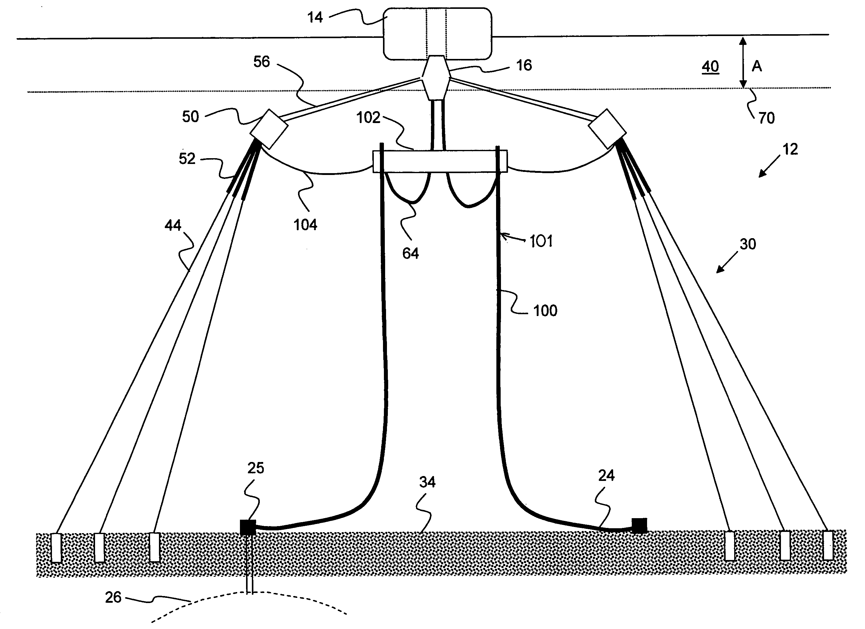
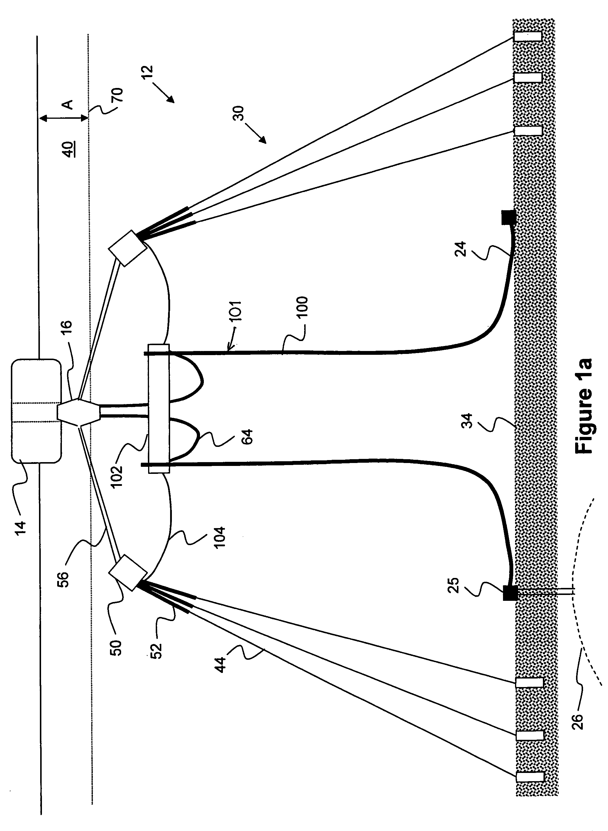
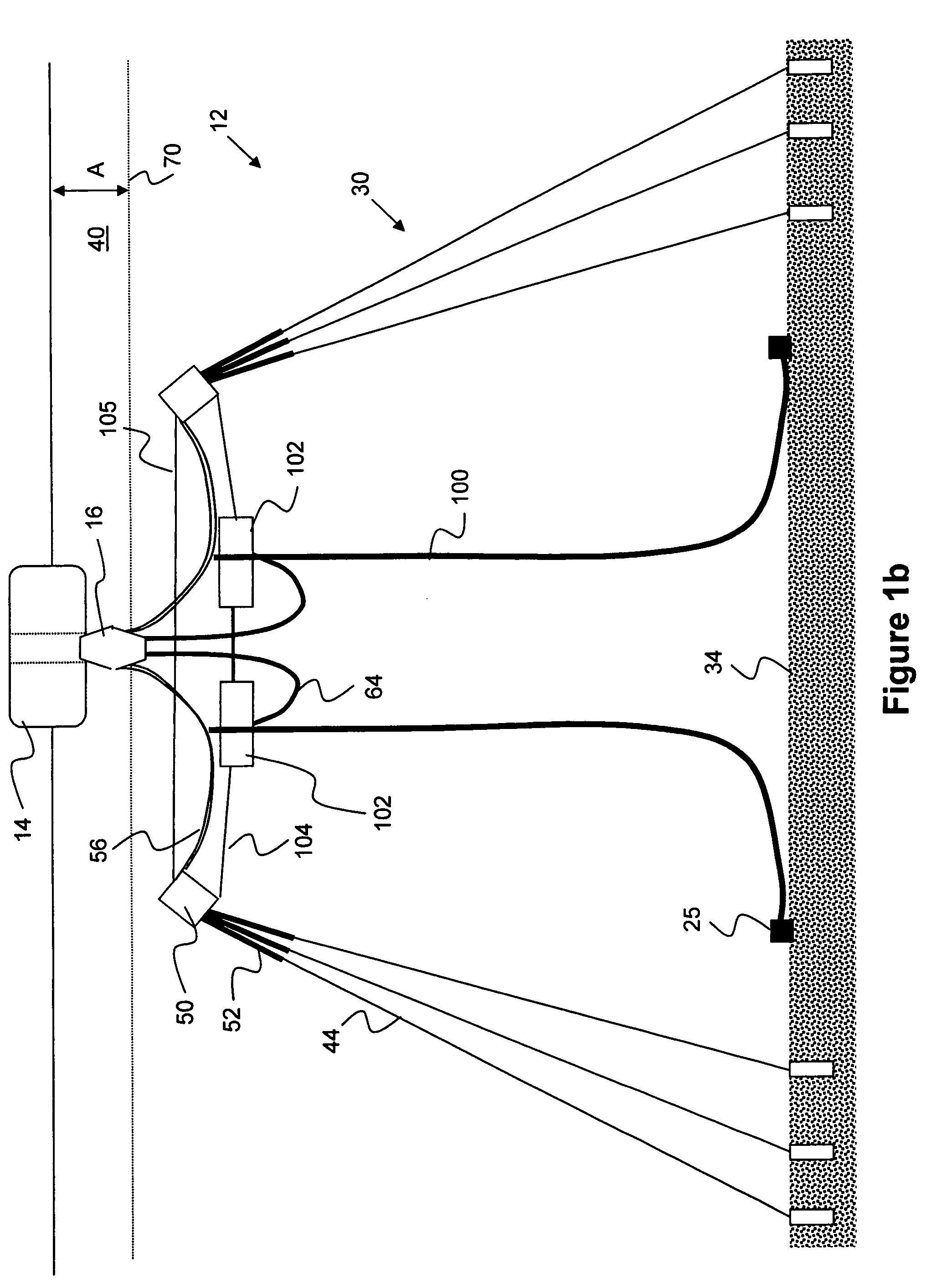
[0018]FIG. 1a illustrates a system 12 for mooring a vessel 14 such as an FPSO (floating, production, storage, and offloading) through a disconnectable turret buoy, or connection buoy, or buoyant connector 16. The system includes risers (production lines, lines for water injection, gas lift, umbilicals) 101 whose lower ends 24 lead to well heads 25 that connect to a subsea hydrocarbon (oil and / or gas) reservoir 26, and also includes mooring assemblies 30 that hold the vessel in position. The risers 101 and mooring or anchor assemblies 30 have upper ends connected to the connection buoy 16, and lower ends connected to the sea floor 34. Thus, all major connections of the vessel to the sea floor are made though the connection buoy 16. There is no primarily vertical tensioned line that extends from the riser buoy 102 to the seabed 34. The vessel sometimes sails away from the location over the reservoir, as when a large storm or iceberg is approaching, or if the vessel sails to a location...


PUM


Abstract

A system is described for use at offshore locations of large depth, for mooring a production vessel or floating unit (14) at a location over a hydrocarbon reservoir (26) and for connecting risers (101) that can be carrying hydrocarbons up from the sea floor to a production vessel that stores the hydrocarbons, flowlines for water injection, gas lift, gas export, umbilicals and mooring lines that moor the vessel. Both the mooring lines and the risers are disconnectably connected to the vessel though a connection buoy, or connector (16). The invention concerns a system that allows a connector (16) to be used that is of minimum mass and volume, to ease its handling especially during its connection and disconnection to and from a vessel.

Description

CROSS-REFERENCE[0001]Applicant claims priority from US Provisional Patent Application Ser. No. 60 / 934,230 filed 12 Jun., 2007.BACKGROUND OF THE INVENTION[0002]Hydrocarbons in an undersea reservoir lying at the bottom of a deep sea (over 500 meters) are commonly produced by an installation that includes risers for carrying the hydrocarbons up from the sea floor to a production vessel that stores the hydrocarbons. The connections to the sea floor can also include flowlines for water injection, gas lift, gas export, and umbilicals, and also mooring lines that moor the vessel. At times the vessel must sail away from a location over the region of the reservoir where the risers and mooring lines are located, as when a storm is approaching, or to carry the stored hydrocarbons to another station, or for another purpose. For this reason, the installation commonly includes a connection buoy, or buoyant connector that is connected to the upper ends of the risers and the upper ends of the moori...

Claims


Application Information

Patent Timeline
IPC IPC(8): B63B22/18
CPCB63B21/50B63B22/02E21B17/012E21B43/0107
Inventor BAUDUIN, CHRISTIANBORDE, BENOITBRAUD, JEAN
Owner SINGLE BUOY MOORINGS INC
Why Eureka
Try Eureka