
System and method for determining electrode-tissue contact based on amplitude modulation of sensed signal

a technology of amplitude modulation and sensed signal, applied in the field of medical probes or instruments, can solve the problems of insufficient the firm effective the inability to accurately determine the extent of the contact between the electrode and the tissue,

Active Publication Date: 2008-12-18
AURIS HEALTH INC
View PDF20 Cites 168 Cited by
  • Summary
  • Abstract
  • Description
  • Claims
  • Application Information

AI Technical Summary

Benefits of technology

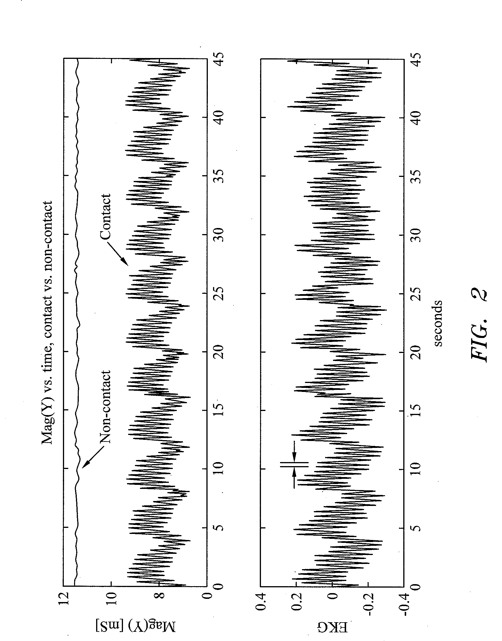
The present invention provides a method and system for monitoring contact between a medical probe and tissue in a patient's body. This is achieved by measuring an electrical parameter, such as electrical admittance, between the probe's electrodes, which is amplitude modulated by the patient's physiological cycle, such as respiratory or heart cycle. The system includes a monitoring device that measures the electrical parameter and a user interface that conveys an output indicative of contact between the probe and tissue based on the amplitude modulation. The technical effects include improved accuracy in detecting contact between the probe and tissue, improved safety during medical procedures, and improved efficiency in performing medical procedures.

Problems solved by technology

While a physician can typically obtain some level of tactile feel for the force created between the instrument and tissue structures during manual manipulations of relatively light-weight instruments such as catheters within the patient, optimal resolution of the sensation maybe inadequate, and with larger instruments, manual sensation of distally-applied forces may be substantially impractical or impossible.
Although the acquisition of impedance measurements has been generally successful in determining when an electrode has been placed in contact with tissue, the variation in impedance of tissue and blood between patients makes it difficult to accurately determine the extent of such electrode-tissue contact.
Thus, during tissue ablation and other diagnostic and / or interventional procedures, firm effective contact between the electrode and tissue, as opposed to insufficient contact between the electrode and tissue, may not always be ascertained.

Method used


Image

  • System and method for determining electrode-tissue contact based on amplitude modulation of sensed signal
  • System and method for determining electrode-tissue contact based on amplitude modulation of sensed signal
  • System and method for determining electrode-tissue contact based on amplitude modulation of sensed signal

Examples


Embodiment Construction

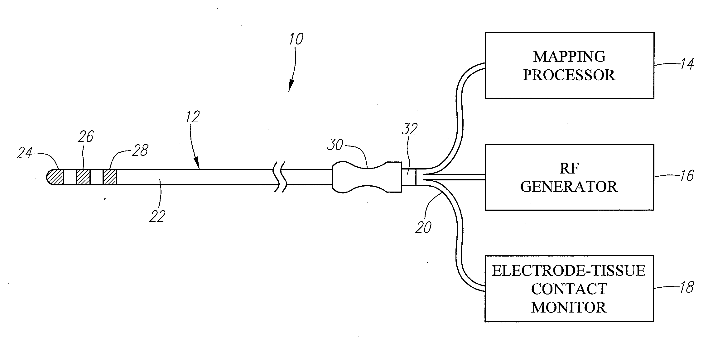
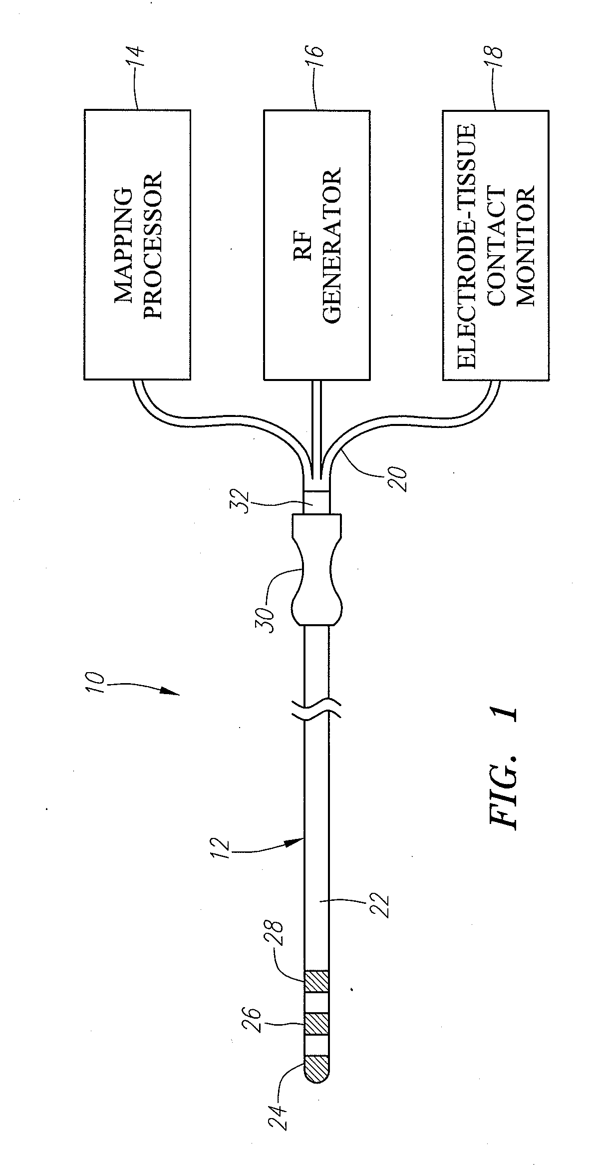
[0023]Referring to FIG. 1, an exemplary electrophysiology (EP) system 10 constructed in accordance with the present inventions is shown. The EP system 10 is particularly suited for mapping a heart by identifying a target tissue site or sites, e.g., aberrant conductive pathways, and for treating the heart by ablating the target tissue site(s). Nevertheless, it should be noted that the concepts disclosed herein may be applied to any process requiring the introduction of a medical probe within a patient's body to diagnose or treat other internal anatomical structures, e.g., the prostrate, brain, gall bladder, uterus, esophagus and other regions in the body.

[0024]The EP system 10 generally comprises a mapping / ablation catheter 12, and a mapping processor 14, a radio frequency (RF) generator 16, and an electrode-tissue contact monitor 18 functionally coupled to the mapping / ablation catheter 12 via a cable assembly 20. The mapping / ablation catheter 12 may optionally be mechanically manipu...


PUM


Abstract

Methods and systems for monitoring contact between a medical probe and tissue are provided. A medical probe is introduced into a patient adjacent the tissue. An electrical parameter, e.g., electrical admittance, is measuring between a first electrode located on the medical probe and a second electrode remote from the first electrode. The electrical parameter is amplitude modulated in response to a physiological cycle of the patient. Contact between the medical probe and the tissue is detected based on the amplitude modulation of the measured electrical parameter.

Description

CROSS REFERENCE TO RELATED APPLICATION[0001]This application is related to U.S. patent application Ser. No. ______ (Attorney Docket No. 20023.01), filed on the same date herewith. The disclosure of this application is expressly incorporated herein by reference.FIELD OF THE INVENTION[0002]The present inventions generally relate to medical probes or instruments, and more particularly to systems and methods for determining contact between a medical probe or instrument and tissue.BACKGROUND OF THE INVENTION[0003]In many procedures, such as minimally-invasive surgery or catheter-based diagnosis and / or intervention, it is important for the physician to know the location of an instrument or probe, such as a diagnostic and / or therapeutic catheter, probe, arm, or other structure relative to the patient's internal anatomy. During cardiovascular catheterization procedures to address electrophysiologic problems, for example, a physician may steer an electrophysiology mapping catheter, typically...

Claims


Application Information

Patent Timeline
Patent Type & Authority Applications(United States)
IPC IPC(8): A61N1/02A61B18/14
CPCA61B5/053A61B18/1492A61B2019/465A61B2090/065
Inventor WILFLEY, BRIAN P.HEANUE, JOSEPH A.FRIEDMAN, STUART L.
Owner AURIS HEALTH INC
Learn More