Cable Stayed Suspension Bridge Making Combined Use of One-Box and Two-Box Girders

a cable-stayed suspension bridge and one-box technology, applied in bridges, bridge construction, bridges, etc., can solve the problems of large diameter of main cables, reduce the distance between the two main cables, prevent the growth of the lifting force generated by the two-box girder, and improve the wind resistance stability of the two-box girder.

Active Publication Date: 2008-12-25
HONSHU-SHIKOKU BRIDGE EXPRESSWAY COMPANY +1
View PDF8 Cites 23 Cited by
  • Summary
  • Abstract
  • Description
  • Claims
  • Application Information

AI Technical Summary

Benefits of technology

[0014](a) The above two-box girder has a central ventilation opening in the central portion as viewed in the transverse direction thereof. When crosswind acts, the wind flows through the central ventilation opening. Thus, the lift force to be generated in the two-box girder can be prevented from growing, so that the critical wind velocity at which fluttering begins to appear is raised, and the wind resistance stability of two-box girder can be improved.
[0015](b) The cable distance between the above two main cables is set almost equal to the width of the central ventilation opening, the plural hanger ropes extend from the main cables almost perpendicularly, and the lower end portion of each hanger rope is connected to near the end portion in the transverse direction of the central ventilation opening in the two-box girder. Owing to this construction, the cable distan

Problems solved by technology

When the two-box girder and the suspension structures are adopted over the entire length of the

Method used


Image

  • Cable Stayed Suspension Bridge Making Combined Use of One-Box and Two-Box Girders
  • Cable Stayed Suspension Bridge Making Combined Use of One-Box and Two-Box Girders
  • Cable Stayed Suspension Bridge Making Combined Use of One-Box and Two-Box Girders

Examples


Embodiment Construction

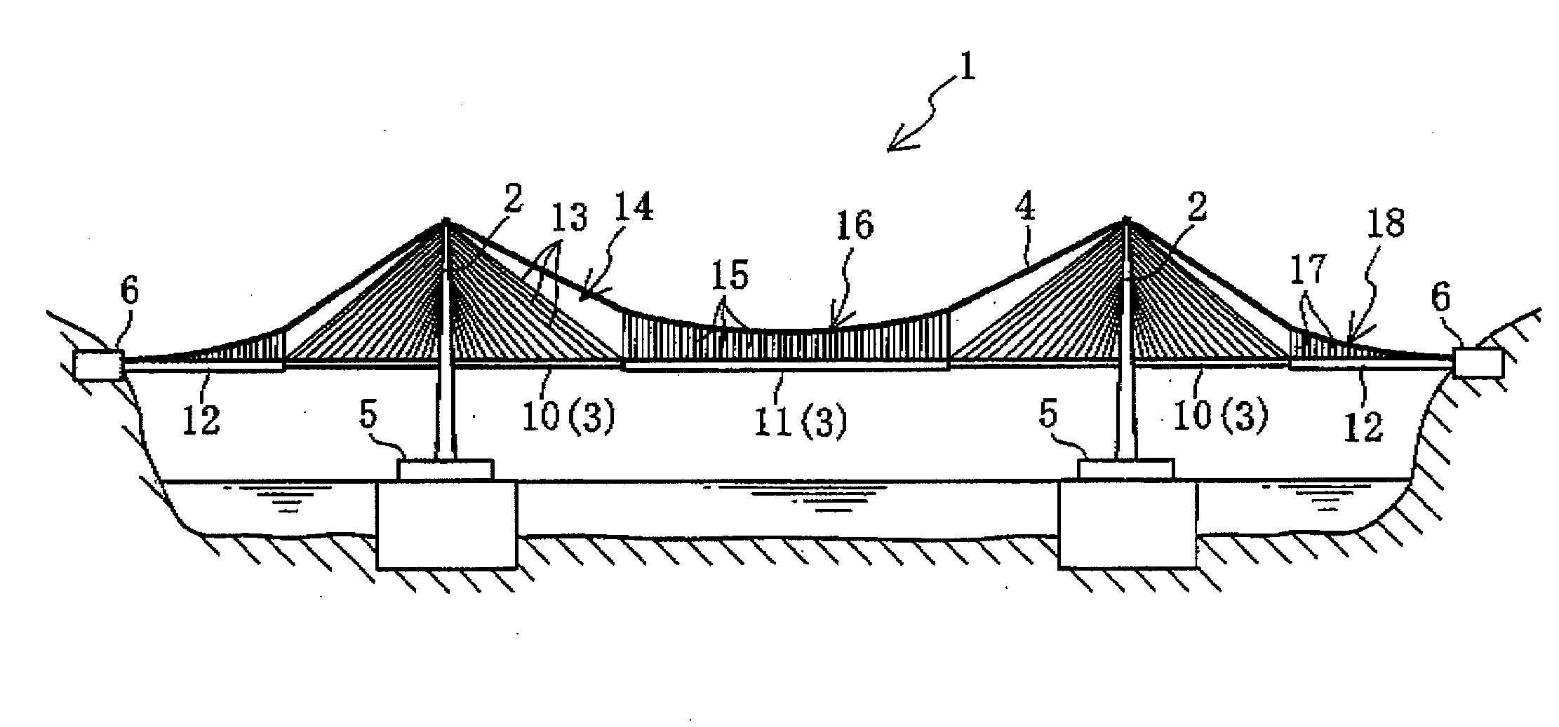
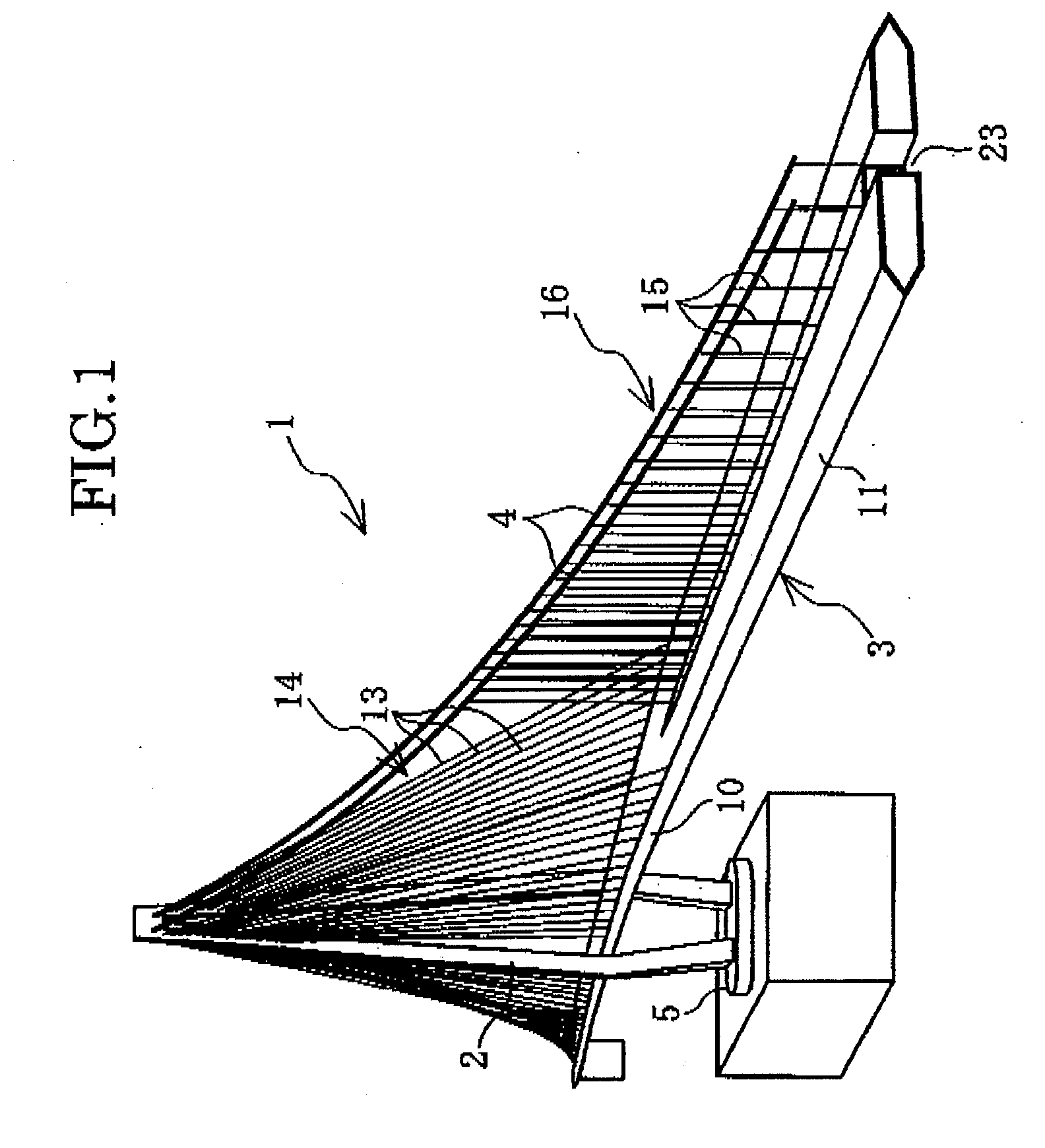
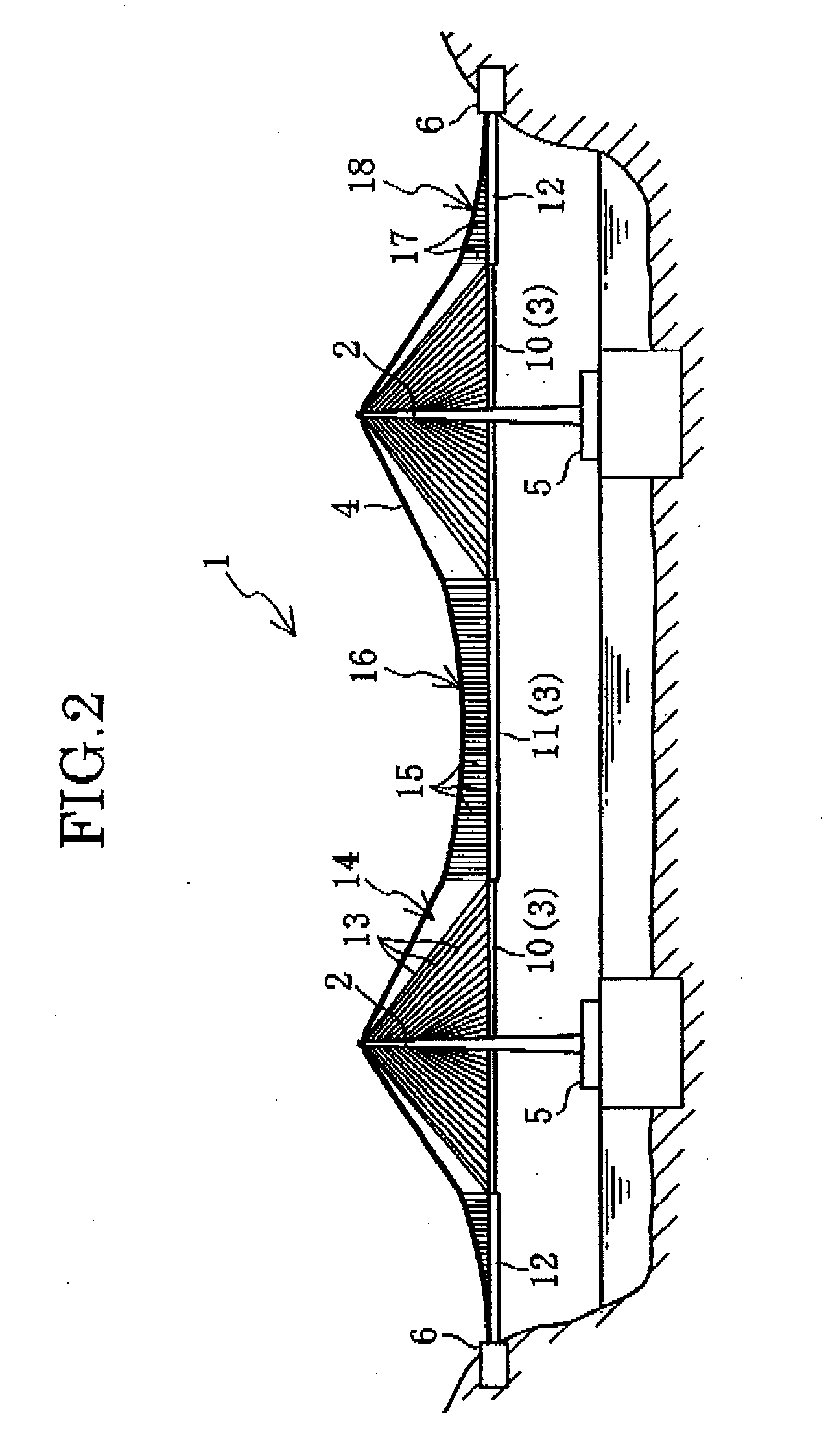
[0040]The present invention relates to the cable stayed suspension bridge using one-box and two-box girders in combination. The best mode of the embodiments that carry out the present invention will be described on the basis of the drawings. FIG. 1 is a perspective view of a principal portion of the cable-stayed suspension bridge 1 using the one-box and two-box girders in combination (hereinafter, referred to as the cable-stayed suspension bridge) according to the present invention. FIG. 2 is a side view of this cable-stayed suspension bridge 1.

[0041]This cable-stayed suspension bridge 1 is a long bridge having 2500 m in length of the center span, and 1250 m in length of the side span, for instance. This cable-stayed suspension bridge 1 comprises two towers 2 set away from each other only by the length of the center span, a bridge girder 3 over the entire length, two main cables 4, two foundation structures 5 that support two towers 2, two anchorage structures 6 that fix the end por...


PUM


Abstract

A cable-stayed suspension bridge having characteristics of a cable stayed bridge and those of a suspension bridge at the same and time and using one-box and two-box girders in combination is disclosed. The bridge grinder of the cable-stayed suspension bridge includes one-box girders that each extend to both sides through the respective one tower and a two-box girder set in a central portion of the center span between towers in the length direction of the bridge girder. The cable-stayed suspension bridge includes cable-stayed structures in which a respective one of the one-box girders is supported by the tower with plural cables and a suspension structure in which the two-box girder is supported by the plural towers with two main cables and plural hanger ropes. The two-box girder has a central ventilation opening in the central portion as viewed in a transverse direction thereof. The hanger ropes in the suspension structure extend from the main cables almost perpendicularly, and their lower end portions are connected to the end portions in the transverse direction of the central ventilation opening or in the vicinity thereof.

Description

TECHNICAL FIELD[0001]The present invention relates to a cable-stayed suspension bridge using one-box and two-box girders in combination, which bridge is suitable as a long and large suspension bridge. In particular, the present invention relates to a cable-stayed suspension bridge using one-box and two-box girders in combination, wherein one-box and two-box girders are employed as a bridge girder, and the one-box girders being set in the cable-stayed bridge area and two-box girders set in the suspension bridge region.BACKGROUND ART[0002]Recently, the cable-stayed bridges and the suspension bridges have become longer and larger. The cable-stayed bridges are advantageous in that they have high torsional rigidity of the bridge girder and excellent wind resistance performance against the crosswind. In addition, the cable-stayed bridge has a simple structure, and is advantageous in the cost of the construction. However, the length of the center span is about 1000 m at most in the cable-s...

Claims


Application Information

Patent Timeline
IPC IPC(8): E01D11/00E01D1/00E01D11/02E01D11/04E01D19/12
CPCE01D11/00
Inventor MURAKOSHI, JUNFUMOTO, KOICHIROSHIMODOI, HIDEKIMIYAZAKI, MASAOSHIRAI, SYUJISUZAWA, MASATO
Owner HONSHU-SHIKOKU BRIDGE EXPRESSWAY COMPANY
Why Eureka
Try Eureka