Flow Rate Measuring Device

a technology of flow rate and measuring device, which is applied in the direction of liquid/fluent solid measurement, volume metering, instruments, etc., can solve the problems of measurement accuracy deterioration and become a cause of failure, and achieve the effect of preventing deterioration in measurement accuracy, long life and convenient maintenan

a technology of flow rate and measuring device, which is applied in the direction of liquid/fluent solid measurement, volume metering, instruments, etc., can solve the problems of measurement accuracy deterioration and become a cause of failure, and achieve the effect of preventing deterioration in measurement accuracy, long life and convenient maintenan

US20080314140A1Active Publication Date: 2008-12-25ORMON CORP +1

Image

  • Flow Rate Measuring Device
  • Flow Rate Measuring Device
  • Flow Rate Measuring Device

Examples


example 1

[0109]As shown in FIG. 13A, the guiding flow channel extending from the secondary flow channel 22a to the inside of the centrifugal chamber 26 was arranged at an angle of 55° with respect to a flow direction of the secondary flow channel 22a, and the number of particles passing through the inside of the detection space portion 23b was calculated.

[0110]Analysis conditions were as follows. 10000 Particles having a diameter of 3 μm were put in at one time under conditions of a particle density of 3000 kg / m3 and an incoming flow rate of 1 L / min. The number of particles that passed the detection space portion 23b was counted. Therefore, it is shown that the smaller the number of particles, the less particles flow into the detection space portion 23b. The calculation results are shown in FIG. 15A.

example 2

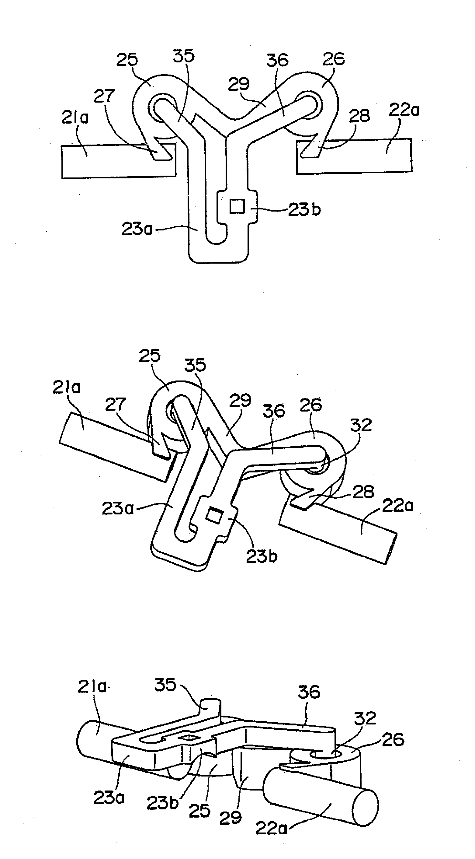
[0113]As shown in FIG. 14A, each of the first and second guiding flow channels 27, 28 was inclined at an angle of 55° with respect to a flow direction of each of the first and second secondary flow channels 21a, 22a, and the intermediate flow channel 29 was formed straight, parallel to the first and second secondary flow channels 21a, 22a.

[0114]Then, particles were put in under the same conditions as those of Example 1. The number of particles passing through the detection space portion 23b was calculated and the number of particles remaining in the flow channels was calculated. The calculation results are shown in FIG. 15B and FIG. 15C.

example 3

[0115]As shown in FIG. 14B, Example 3 is almost the same as Example 2 described above. A difference is that the intermediate flow channel 29 was bent at an angle of 80° to form a generally V-shape.

[0116]Then, particles were put in under the same conditions as those of Example 1. The number of particles passing through the detection space portion 23b was calculated and the number of particles remaining in the flow channels was calculated. The calculation results are shown in FIG. 15B and FIG. 15C.


PUM


Abstract

A flow rate measuring device has a flow channel including: a pair of first and second centrifugal chambers each having a curved wall surface; a first guiding flow channel allowing a first secondary flow channel to communicate with one end of the wall surface of the first centrifugal chamber; an intermediate flow channel allowing the other end of the wall surface of the first centrifugal chamber to communicate with one end of the wall surface of the second centrifugal chamber; a second guiding flow channel allowing the other end of the wall surface of the second centrifugal chamber to communicate with a second secondary flow channel; a first flow dividing channel communicating with the first centrifugal chamber a second flow dividing channel communicating with the second centrifugal chamber; and a detection space portion, in which a detection element is placed.

Description

TECHNICAL FIELD[0001]The present invention relates to a flow rate measuring device, for example, a small sized flow rate measuring device used for an industrial equipment for monitoring an air flow rate in factories, a medical equipment such as a therapeutic instrument for sleep apnea syndrome.BACKGROUND ART[0002]Conventionally, a flow rate measuring device has a construction in which a detection element is placed in a flow channel and an air flow rate is measured. However, if the flow rate measuring device is used for a long term, dust in air adheres to and accumulates on the detection element, and measurement accuracy deteriorates. This may become a cause of failure.[0003]In order to eliminate such a defect, there is a dust trap device having a structure in which trap walls are provided in a flow channel, dust in an airflow is caught by the trap walls so as to be separated by means of utilizing an inertial force of dust that goes straight, and only a clean airflow is led to the de...

Claims


Application Information

Patent Timeline
25 Dec 2008
Publication
US20080314140A1
IPC
G01F1/00
CPC
G01F1/684; G01F5/00; G01F15/12; G01F15/14
Inventors
UEDA, NAOTSUGU; NOZOE, SATOSHI