Driving Piston Maintaining Structure in Gas Nailer

a technology of driving piston and maintaining structure, which is applied in the field of gas nailers, can solve the problems of reducing the supercharging effect itself, unable to carry out supercharging operation, and affecting the operation of driving piston stroke loss

Inactive Publication Date: 2008-12-25
MAX CO LTD
View PDF36 Cites 25 Cited by
  • Summary
  • Abstract
  • Description
  • Claims
  • Application Information

AI Technical Summary

Benefits of technology

[0006]The present invention provide a countermeasure for preventing a driving piston from moving downward during a supercharging operation in a gas nailer having a supercharging device. More specifically, a structure for maintaining a driving piston i

Problems solved by technology

When the driving piston is pressed to move downward, a problem arises in that a stroke loss of the driving piston occurs and the supercharging effect itself reduces because the pressure increase in the combustion chamber is substantially disturbed.
In some cases, the supercharging operation cannot be carried out.
Then, in the known internal combustion type tool for hammering the fastener having the supercharging device, there is not provided a particular countermeasure for solving the above-described problem.
However, it is difficult to set an adequate locking load for braking the driving piston when re

Method used


Image

  • Driving Piston Maintaining Structure in Gas Nailer
  • Driving Piston Maintaining Structure in Gas Nailer
  • Driving Piston Maintaining Structure in Gas Nailer

Examples


first embodiment

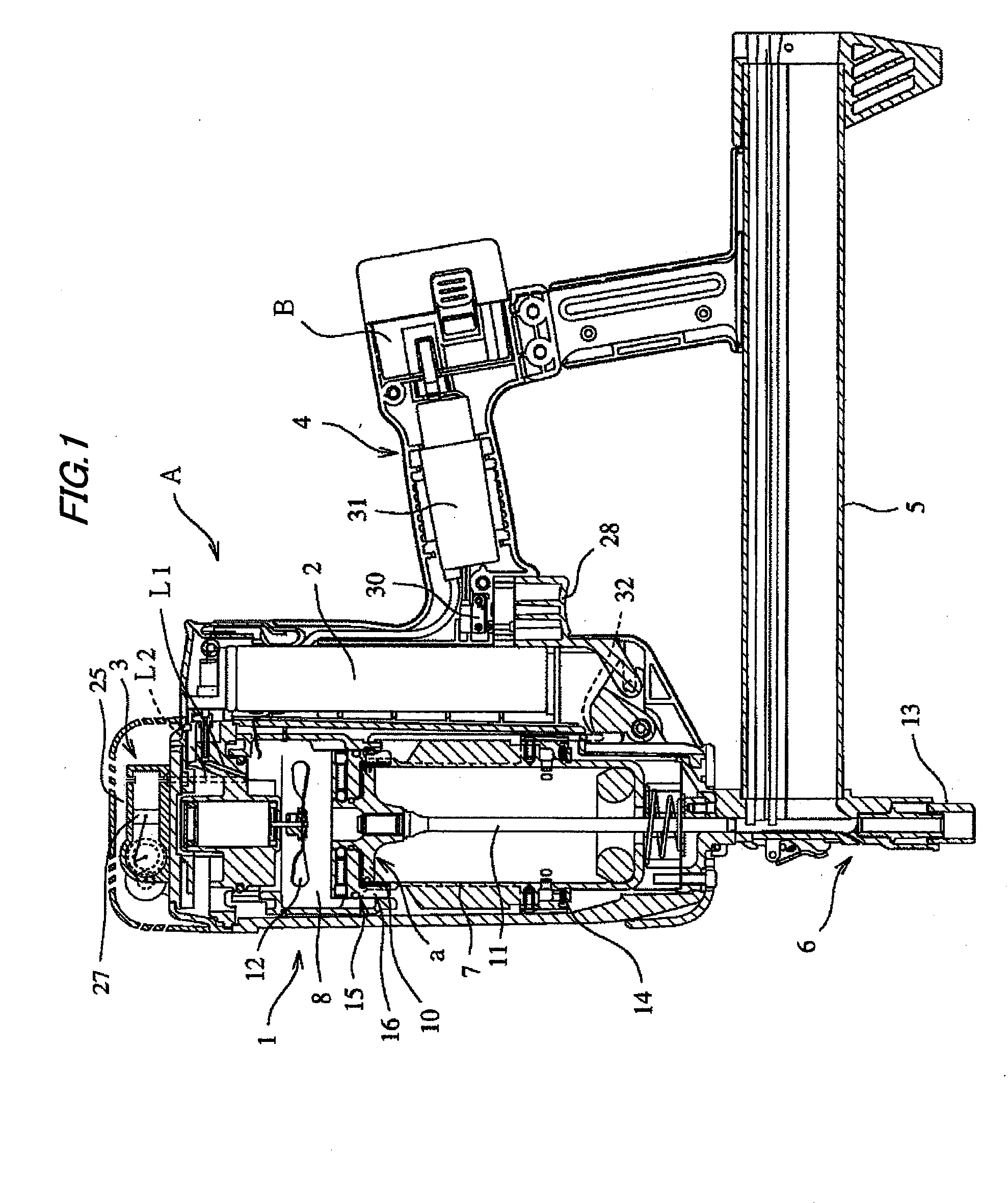
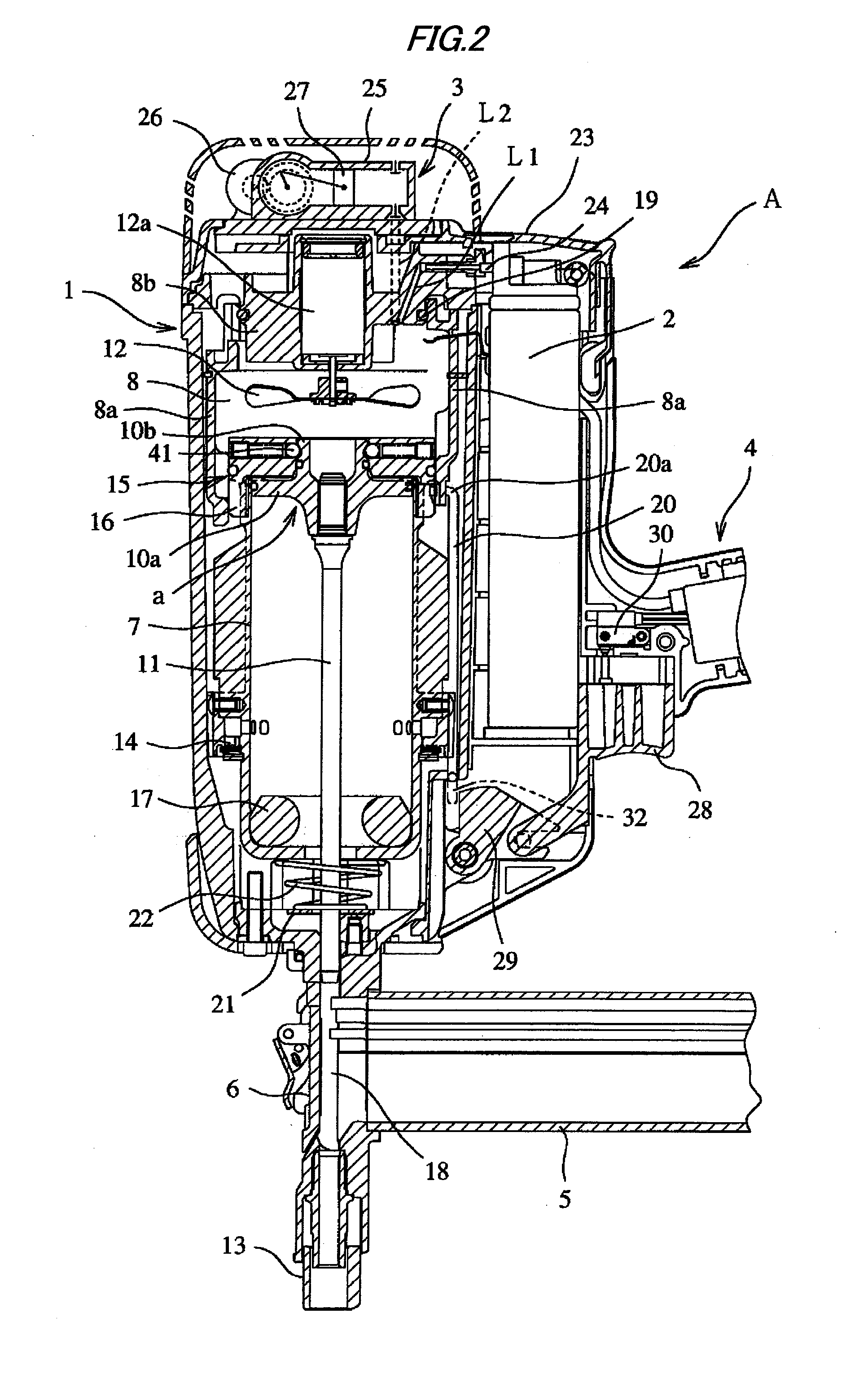
[0036]A first embodiment of the invention will be described with reference to FIGS. 1 to 3.

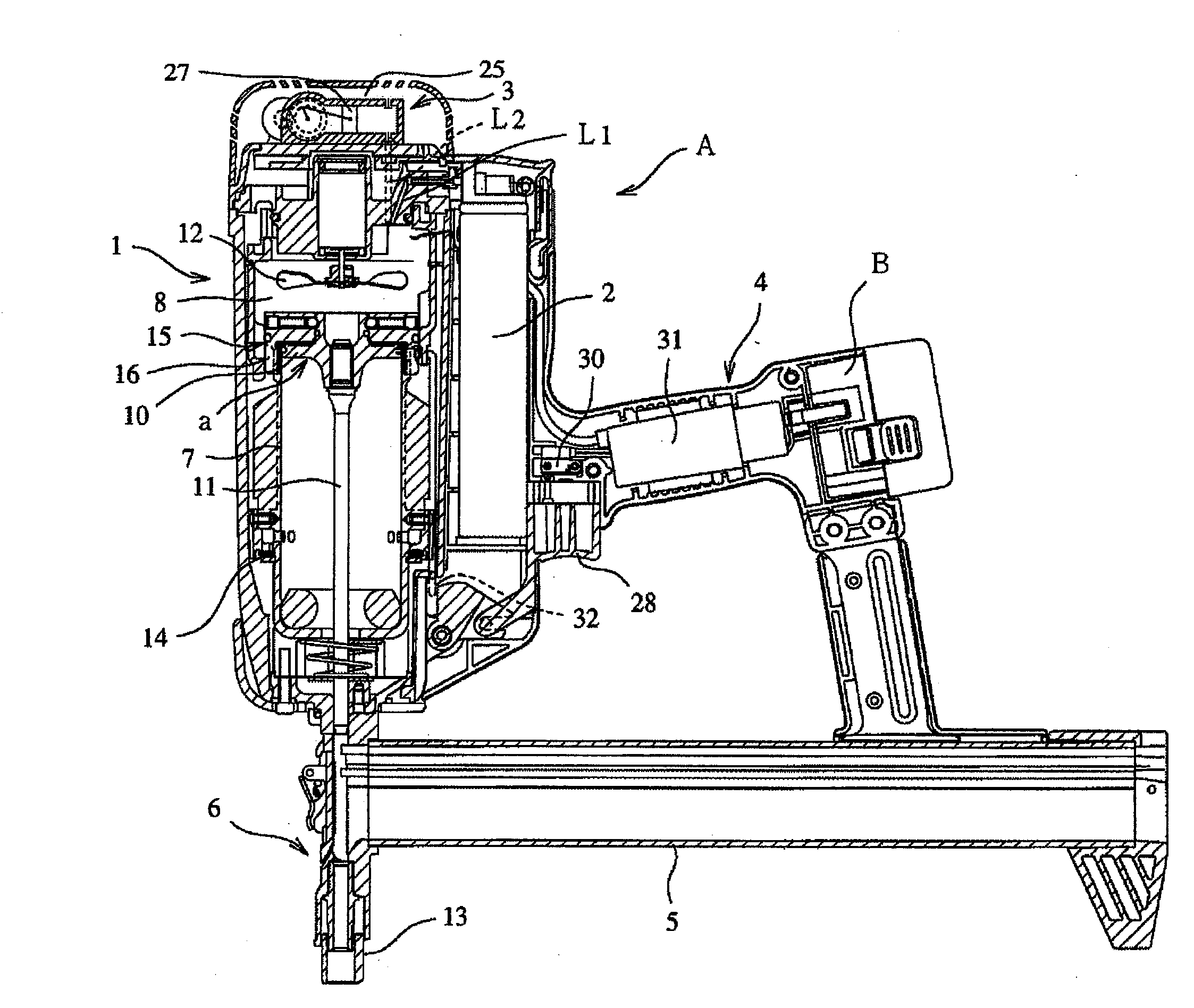
[0037]As shown in FIGS. 1 and 2, a gas nailer A according to the invention includes a nailer body 1 which has therein a driving mechanism a, a gas fuel cartridge 2, a supercharging device 3, and the like, a grip 4 which is integrally formed with the nailer body 1, and a nose part 6 which has a magazine portion 5 formed in the lower portion of the nailer body 1 in a protruding manner. In addition, although the nailer is described in the embodiments of the invention, the invention is not limited to the nailer, but may be applied to other tools for hammering other fasteners such as a hammered screw.

[0038]Then, the driving mechanism a received in the nailer body 1 includes a driving cylinder 7, a combustion chamber 8 which is disposed above the driving cylinder 7, a driving piston 10 which slidably reciprocates in the driving cylinder 7, a nailer driver 11 of which one base end (upper end shown in...

second embodiment

[0086]As shown in FIGS. 4 and 5, the driving piston 10 according to the second embodiment has a structure in which the outer periphery of the driving piston 10 slides on the inner wall of the driving cylinder 7 through a seal ring 43 and an annular protruding portion 44 is formed in the upper portion of the driving piston 10. The annular protruding portion 44 formed in the upper portion of the driving piston 10 protrudes from the upper portion of the driving cylinder 7 by a predetermined height when the driving piston 10 is located at TDC.

[0087]An annular concave groove 46 is formed in the outer periphery of the annular protruding portion 44 formed in the upper portion of the driving piston 10 so as to be used for the locking action carried out by the locking device 15. When the pressing member 41 as the spherical member of the locking device 15 is locked to the annular concave groove 46, the driving piston 10 is maintained at the predetermined position under the predetermined locki...

third embodiment

[0099]FIG. 6 shows the structure for maintaining the driving piston according to the third embodiment, which shows a modified example of the structure for maintaining the driving piston 10 according to the first embodiment. Additionally, the locking device 15 locks or unlocks the driving piston 10 by using a solenoid 57.

[0100]The locking device 15 is configured such that a pressing member 60 having a spherical front end and pressed by a spring 58 can slide along a hole portion 59 by using the solenoid 57. When the driving piston 10 is locked so as to maintain the driving piston 10 at the predetermined position, the solenoid 57 is demagnetized by turning off electric current to the solenoid 57 so that the front end of the pressing member 60 is pressed to a locking groove 49 of the driving piston 10 by the urging force of the spring 58.

[0101]In addition, when releasing the locking action for locking the driving piston 10, the solenoid 57 is magnetized by turning on electric current to...


PUM


Abstract

A gas nailer is provided with a driving cylinder 7, a driving piston 10, a combustion chamber 8, a gas fuel cartridge 2, and a supercharging device 3. The driving piston 10 is operated in the driving cylinder 7 by a combustion pressure generated when a mixture of gas fuel and air is burned in the combustion chamber 8, and a driver hammers a fastener by an operation of the driving piston. A locking device 15 for locking the driving piston 10 is provided in the driving cylinder 7 so as not to move the driving piston 10 in accordance with a pressure increase in the combustion chamber 8 during a supercharging operation in which compressed air is supplied by the supercharging device 3.

Description

TECHNICAL FIELD[0001]The present invention relates to a gas nailer as an internal combustion type tool for hammering a fastener such as a nail or a hammered screw, and more particularly, to a structure for maintaining a driving piston of the gas nailer which prevents the driving piston from moving in accordance with a pressure increase in a combustion chamber during a supercharging operation.BACKGROUND ART[0002]Conventionally, there is known an internal combustion type tool (gas nailer) for hammering a faster, such as a nail or a screw, having a supercharging device for improving a driving force. In the known internal combustion type tool for hammering the fastener, in order to start hammering the fastener, an operation member is operated in response to a pressing action of a front end of the tool to a workpiece. Subsequently, a driving piston of a fuel storage chamber of the supercharging device is operated by an action of the operation member. Subsequently, pressurized supercharge...

Claims


Application Information

Patent Timeline
IPC IPC(8): B25C1/14
CPCB25C1/08B25C1/00
Inventor TAMURA, JUNICHITAKEMURA, HAJIMEMURAYAMA, KATSUHIKO
Owner MAX CO LTD
Why Eureka
Try Eureka