Water heater stacking detection and control

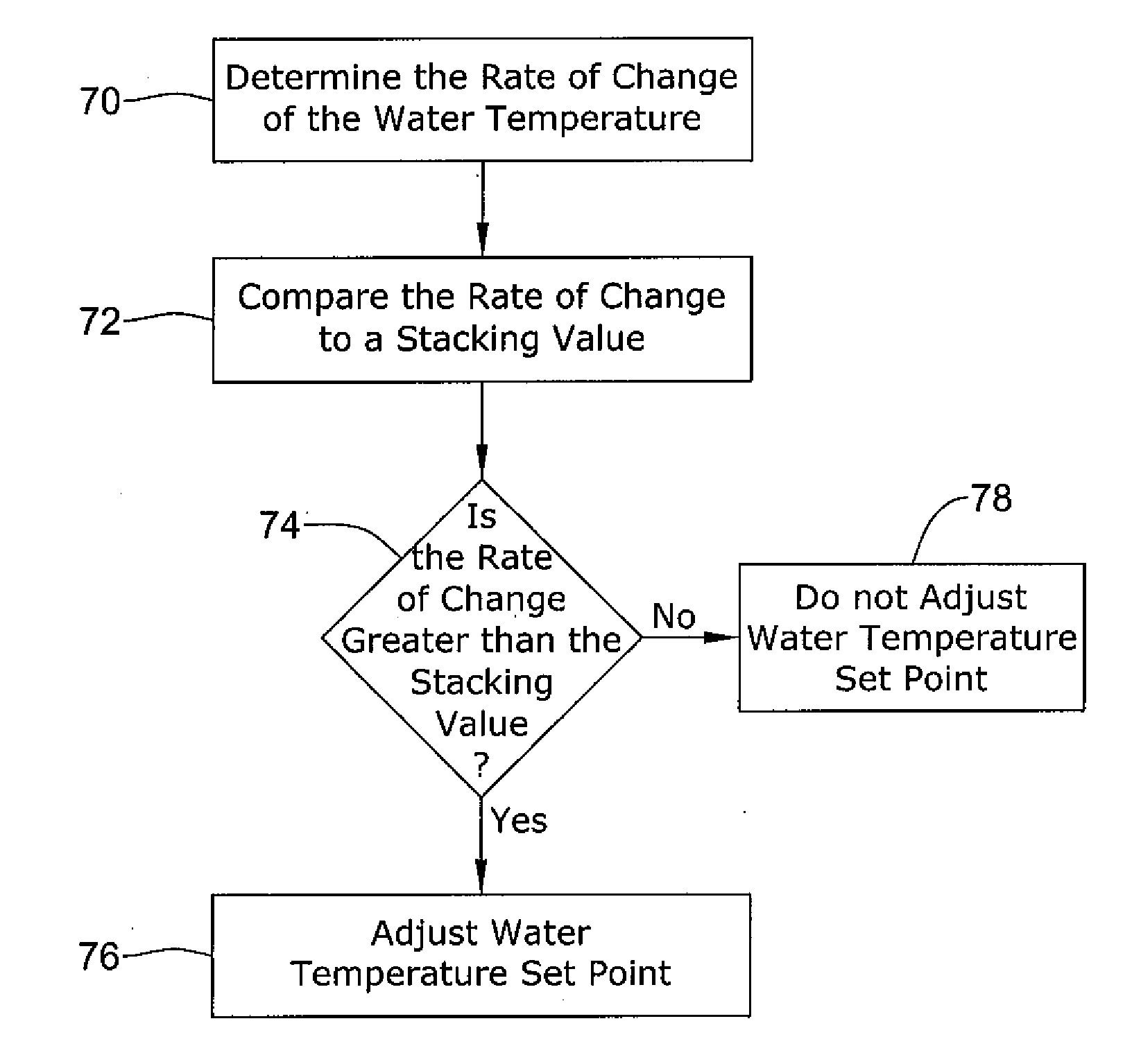
a technology for water heaters and stacking, applied in the field of controllers and methods for controlling water heaters, can solve the problems of water heaters, water heater tanks may be particularly susceptible to stacking, and relatively short heating cycles, so as to limit the effect of stacking and reduce the water temperature set point

Active Publication Date: 2008-12-25
ADEMCO INC
View PDF81 Cites 36 Cited by
  • Summary
  • Abstract
  • Description
  • Claims
  • Application Information

AI Technical Summary

Benefits of technology

[0008]The present invention relates generally to water heaters, and more particularly, to controllers and methods for controlling water heaters. In one illustrative embodiment, a method of operating a water heater to limit the effects of stacking may include sensing the temperature of the water in the water heater tank with a sensor, determining if stacking is likely to be occurring in the water heater tank using the sensed water temperature, and adjusting the water temperature set point if stacking is occurring in the water heater tank. In some cases, the water temperature set point may be lowered if stacking is likely to be occurring, at least temporarily. In some cases, the controller may determine if stacking is likely to be occurring in the water heater by comparing the rate of change of the water temperature sensed by the sensor with a threshold rate of change (or other value).

Problems solved by technology

Water heaters with a single temperature sensor located at or near the bottom of the water heater tank may be particularly susceptible to stacking.
Because only a relatively small amount of colder water may be located at or near the bottom of the water heater tank, particularly in short water draw situations, the resulting heating cycles may be relatively short.
This operation can create and / or exacerbate water “stacking” in the water heater, which in many cases, is undesirable.

Method used


Image

  • Water heater stacking detection and control
  • Water heater stacking detection and control
  • Water heater stacking detection and control

Examples


Embodiment Construction

[0019]The following description should be read with reference to the drawings wherein like reference numerals indicate like elements throughout the several views. The detailed description and drawings show several embodiments which are meant to be illustrative of the claimed invention.

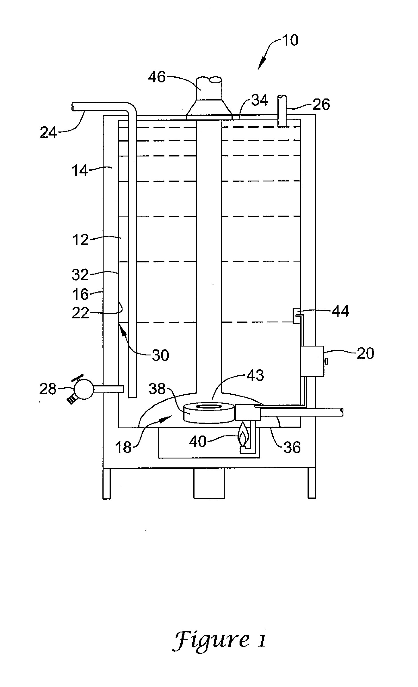
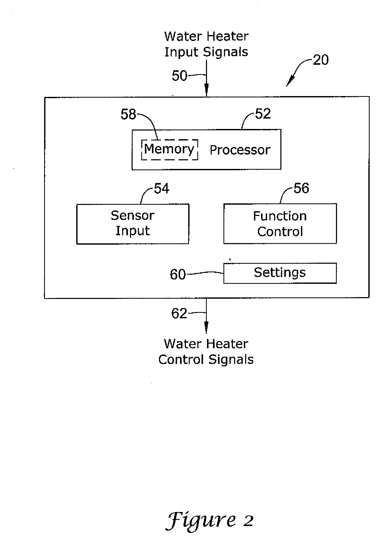
[0020]The present invention relates generally to water heaters, and more particularly, to controllers and methods for controlling water heaters. FIG. 1 is cutaway view of an illustrative water heater 10. The illustrative water heater 10 includes a tank 12, an insulating layer 14, an external shell 16, a heater 18, and a controller 20. Tank 12 holds water that is to be heated and may be constructed of steel or other heat conducting material. Illustrative tank 12 has an inner surface 22, an input supply tube or dip tube 24, an output conduit or pipe 26, a drainage valve 28, a rust inhibiting liner 30, and an outer surface 32.

[0021]Insulating layer 14 may be located between outer surface 32 of tank 12 and...


PUM


Abstract

Methods and systems for operating a water heater to limit the effects of stacking in a water heater tank are disclosed. In some cases, the water heater controller may determine a rate of change of the water temperature in the water heater tank. If the rate of change exceeds a threshold value, the controller may adjust the water heater temperature set point downward to help reduce stacking in the water heater. In some cases, the water heater temperature set point may be returned to the original water heater temperature set point when stacking is no longer likely to be of a concern. In one illustrative embodiment, the controller may track the time that the heater of the water heater is in the “on” state, or the time that the heater is in the “off” state, during subsequent heating cycles. The controller may then compare the “on” time or the “off” time to respective recovery threshold times. If the “on” time or the “off” time exceeds its respective recovery threshold time, then the controller may adjust the set point toward the original water heater temperature set point, sometimes in an incremental manner.

Description

FIELD [0001]The present invention relates generally to water heaters, and more particularly, to controllers and methods for controlling water heaters.BACKGROUND [0002]Water heaters are commonly used in homes, businesses and just about any establishment that has a need for heated water. Water heaters often heat water using the simple “heat rises” principle. In operation, water heaters typically heat cold or ambient temperature water entering at or near the bottom of the water heater tank to a desired temperature using a gas-fired burner, an electric heater or some other heater element. During a heating cycle, the cold or ambient temperature water at or near the bottom of the water heater tank becomes hotter and begins to rise towards the top of the water heater tank. Cooler and denser water, once on top of the water being heated, falls toward the bottom of the water heater tank so that it can be heated or reheated to the desired temperature. After the temperature of the water at the ...

Claims


Application Information

Patent Timeline
Patent Type & Authority Applications(United States)
IPC IPC(8): G05D23/01
CPCF28D20/0034G05D23/1919F24H9/2007F24H9/2035F24H1/206
Inventor STRAND, ROLF L.
Owner ADEMCO INC
Why Eureka
Try Eureka