Autostereoscopic Display Device

a display device and display technology, applied in the field of display devices, can solve the problems of image distortion and image not being displayed correctly to the user, and achieve the effect of low complexity and different densities

Active Publication Date: 2008-12-25
KONINKLIJKE PHILIPS ELECTRONICS NV
View PDF7 Cites 27 Cited by
  • Summary
  • Abstract
  • Description
  • Claims
  • Application Information

AI Technical Summary

Benefits of technology

[0006]This allows the display device to be adjusted in accordance with the user head movements, in order to display an autostereoscopic, three dimensional image correctly. Preferably, each lens element is elongated and covers a linear segment of the imaging layer f...

Problems solved by technology

If the user moves his head, and thereby his eyes, out of the predetermined position, the image will be ...

Method used


Image

  • Autostereoscopic Display Device
  • Autostereoscopic Display Device
  • Autostereoscopic Display Device

Examples


Embodiment Construction

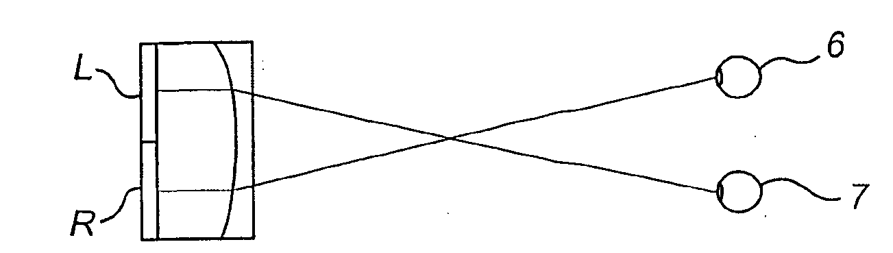
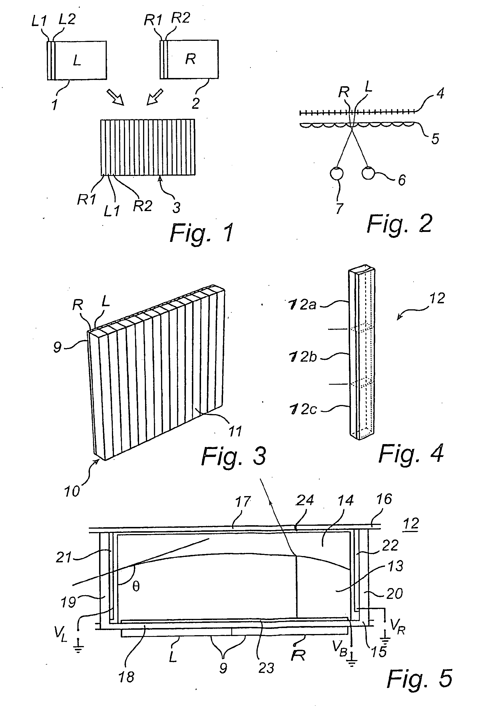
[0024]FIGS. 1 and 2 illustrate schematically a concept for obtaining an autostereoscopic image. By an autostereoscopic image is meant an image that to a user appears to be 3-dimensional, without the use of special glasses.

[0025]With reference to FIG. 1, a first image 1 is intended to be displayed to the left eye of a user, whereas a second image 2 is intended to be displayed to the right eye of a user. Such images may be obtained e.g. by photographing an object with two offset cameras, much like the human eyes. It is of course possible to obtain such images in many other ways.

[0026]From the first and second images 1, 2 a composite image 3 may be obtained by interleaving thin vertical slices L1, L2, etc.; R1, R2, etc. from the first and second images 1, 2 in an ordered manner (from left to right: leftmost slice from second image, leftmost slice from first image, second leftmost slice from second image etc.). The composite image may be displayed e.g. using a liquid crystal display (LC...


PUM


Abstract

The present invention relates to an autostereoscopic display device, comprising an imaging layer (9) and a lens layer (10). The lens layer (10) serves to project different content from the imaging layer (9) to the left and right eyes, respectively, of a user. The lens layer (10) comprises lens cells (12), enclosing two fluids (13, 14) with different refractive indices. The shape of the interface between the fluids may be changed using electrowetting, by means of two individually controllable electrodes (21, 22) at the sides of each lens cell (12). The display device further comprises a user head tracking device and means for controlling the lens cell electrodes depending on a detected user head position. This allows the display device to display a correct 3D-image, even if the user moves his head.

Description

FIELD OF THE INVENTION[0001]The present invention relates to a display device, comprising an imaging layer with a plurality of picture elements and a lens layer comprising a plurality of lens elements for projecting light from different picture elements in the imaging layer to the left and right eyes of a user in order to provide an autostereoscopic effect, wherein each lens element comprises at least one lens cell which defines a closed space, having a front wall, facing the user, a back wall facing the imaging layer and side walls, connecting the back and front walls, the closed space being filled with first and second substantially immiscible fluids having different refractive indices, each cell comprising means for varying the shape of the interface between the first and second fluidsBACKGROUND OF THE INVENTION[0002]Such a device, based on the so called electrowetting effect, is disclosed in WO, 03 / 071335, A2. In order to provide a correct autostereoscopic image in such devices,...

Claims


Application Information

Patent Timeline
IPC IPC(8): H04N13/04H04N13/00
CPCG02B26/005H04N13/305H04N13/30H04N13/373H04N13/376H04N13/00
Inventor VOS, GERARDUS JOHANNES JOSEPHUSKUIPER, STEINHENDRIKS, BERNARDUS HENDRIKUS WILHELMUSVAN RENS, BAS JAN EMILE
Owner KONINKLIJKE PHILIPS ELECTRONICS NV
Why Eureka
Try Eureka