Tracking type laser interferometer and method for resetting the same

a laser interferometer and tracking technology, applied in the field of tracking laser interferometer and a method for resetting the same, can solve the problems of adversely affecting the accuracy of high-quality measurement, and achieve the effect of preventing environmental fluctuations due to human intervention, accurate and stable measuremen

Inactive Publication Date: 2008-12-25
MITUTOYO CORP
View PDF5 Cites 68 Cited by
  • Summary
  • Abstract
  • Description
  • Claims
  • Application Information

AI Technical Summary

Benefits of technology

[0024]According to the present invention, by providing a light irradiator and a light receptor to the configuration of the conventional laser interferometer, it becomes possible to automatically reset tracking without any manual work when the tracking is disabled due to a reason such as interru

Problems solved by technology

In addition, since the work is manually carried out, a change in temperature and generation of vibrations and foreign substances due to movement of a human being at this time become factors to change the measurement environment, whe

Method used


Image

  • Tracking type laser interferometer and method for resetting the same
  • Tracking type laser interferometer and method for resetting the same
  • Tracking type laser interferometer and method for resetting the same

Examples


embodiment 1

[0035]First, a description is given of Embodiment 1 of the present invention using FIG. 3 and FIG. 4. FIG. 3 is a perspective view showing the entire configuration of a tracking type laser interferometer according to the present embodiment, and FIG. 4 is a brief sectional view of the main body portion of a tracking type laser interferometer, which shows the position of the same interferometer.

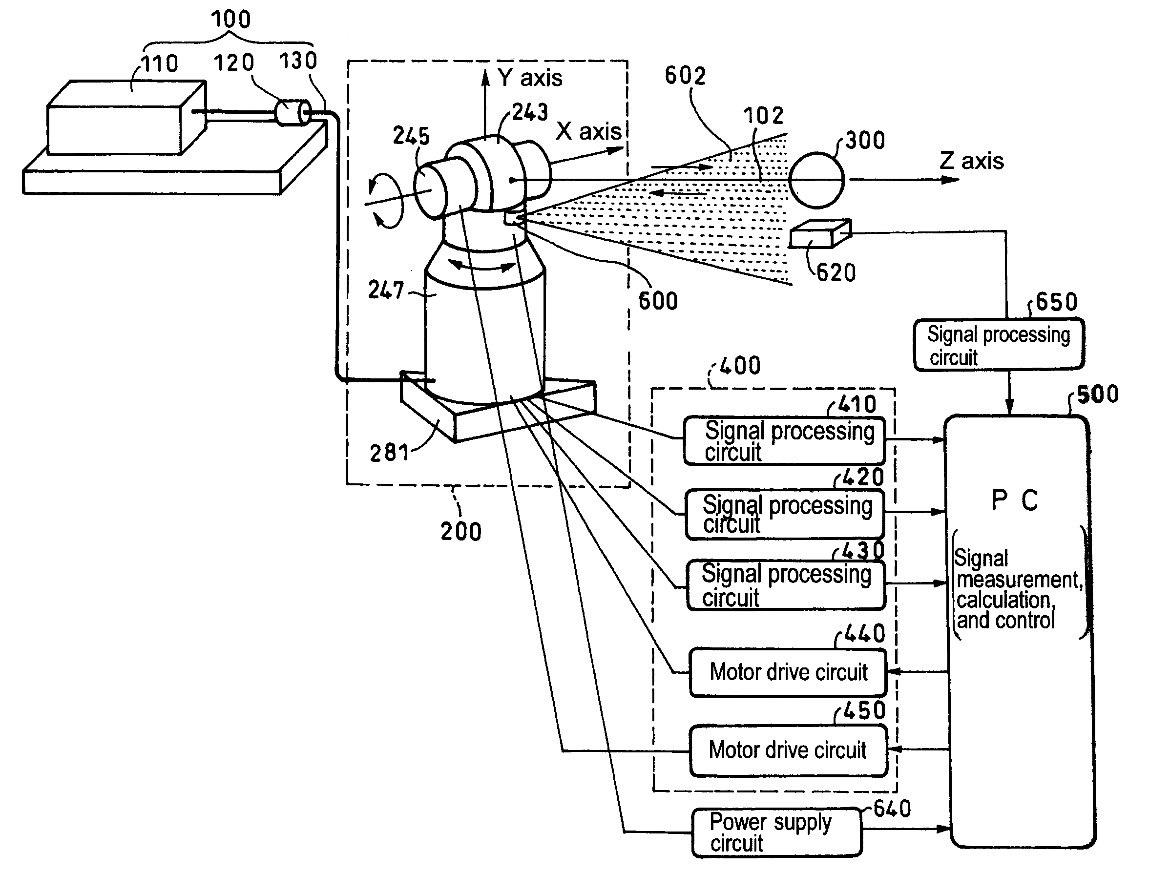
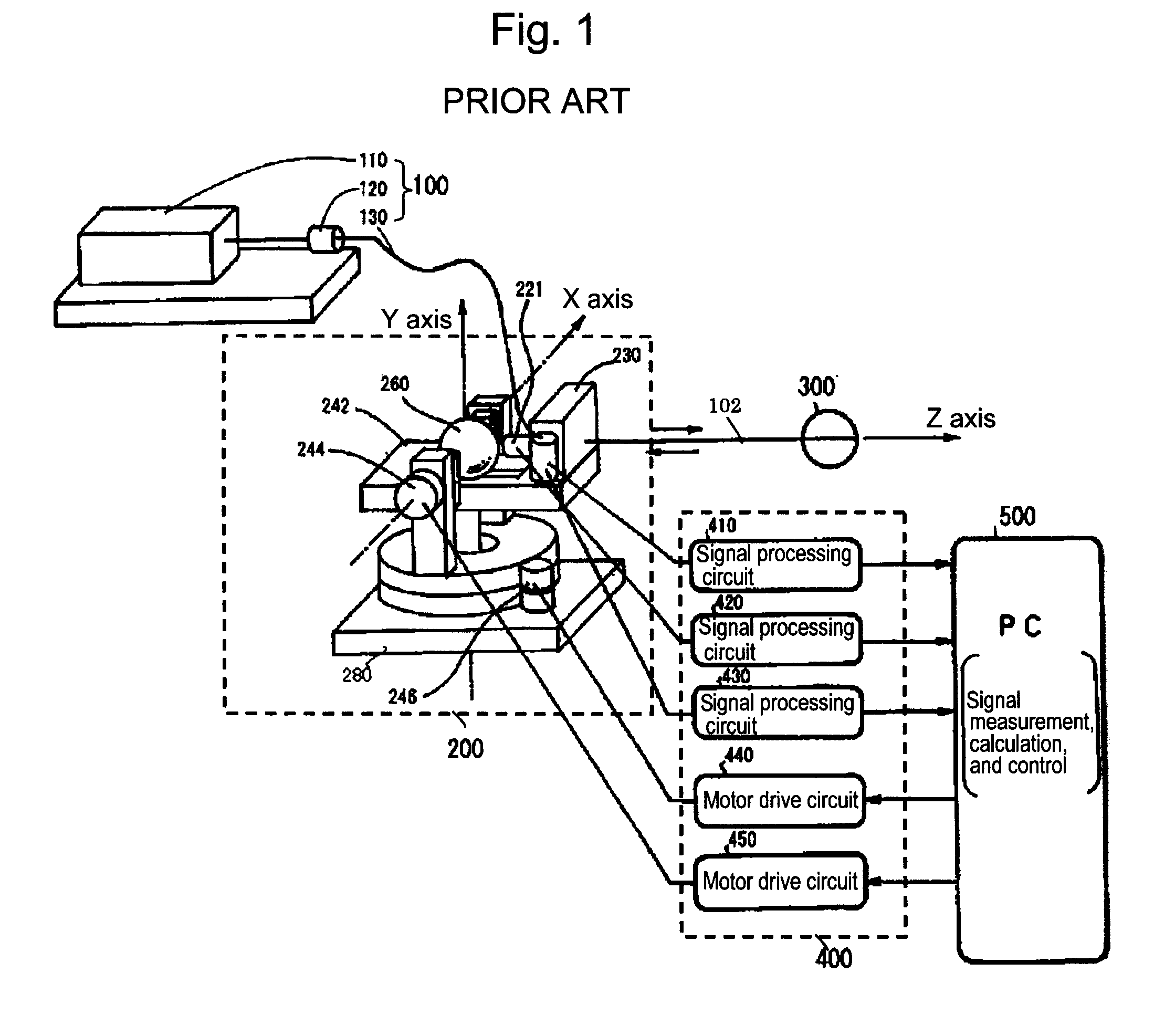
[0036]As shown in FIG. 3, the present embodiment is provided with a light source portion 100, a main body portion 200, a retroreflector 300, a circuit portion 400, and a PC 500, which are main components of a conventional homodyne tracking type laser interferometer, and is further provided with a light irradiator 600, and a reflector 610 (not illustrated), which are characteristic components of the present embodiment, in the main body portion 200, and further includes a light receptor 620, a power supply circuit 640, and a signal processing circuit 650. Hereinafter, although a description is om...

embodiment 2

[0052]Next, a description is given of Embodiment 2 of the present invention, using FIG. 5 and FIG. 6. FIG. 5 is a perspective view showing the entire configuration of a tracking type laser interferometer according to the present embodiment, and FIG. 6 is a brief configurational view showing a light detector of the same interferometer.

[0053]As shown in FIG. 5, the present embodiment is provided with a light source portion 100, a main body portion 200, a retroreflector 300, a circuit portion 400, and a PC 500, which are main components of a conventional homodyne tracking type laser interferometer, and is further provided with a light detector 660, and a reflector 610 (not illustrated), which are characteristic components of the present embodiment, in the main body portion 200, and further includes a power supply circuit 640 and a signal processing circuit 650. That is, in the present embodiment, the light detector 660 is provided instead of the light irradiator 600 and the light recep...


PUM


Abstract

A tracking type laser interferometer that detects displacement of a retroreflector 300 being an object to be measured by utilizing interference of a laser beam 102 irradiated onto the retroreflector 300 and reflected by the retroreflector 300 in the returning direction, and carries out tracking by means of a two-axis turning mechanism 240 using displacement in the position of the optical axis of the laser beam 102; the same tracking type laser interferometer, includes; a light irradiator 600 that emits a fan-shaped laser light 602 that is fan-shaped including the optical axis of the laser beam 102, is interlocked with turning movements of the two-axis turning mechanism 240 around an axis orthogonal to the center axis of the corresponding fan shape; and a light receptor 620 that has a specific positional relationship with the retroreflector 300 or the light irradiator 600 and receives the fan-shaped laser light. Thereby, tracking can be automatically reset when the tracking is disabled due to a reason such as interruption of laser light or initial adjustment work can be automated when commencing measurement.

Description

CROSS-REFERENCE TO RELATED APPLICATION[0001]The disclosure of Japanese Patent Application No. 2007-162295 filed on Jun. 20, 2007 including specifications, drawings and claims is incorporated herein by reference in its entirety.BACKGROUND OF THE INVENTION[0002]1. Field of the Invention[0003]The present invention relates to a tracking type laser interferometer and a method for resetting the same, and in particular, to a tracking type laser interferometer and a method for resetting the same, which are preferable for a tracking type laser interferometer that detects displacement of a retroreflector being an object to be measured by utilizing interference of a laser beam, which is irradiated onto the retroreflector and is reflected by the retroreflector in the returning direction, and carries out tracking by means of a two-axis turning mechanism using a change in the position of the optical axis of the laser beam, and are capable of automatically resetting the laser interferometer to a t...

Claims


Application Information

Patent Timeline
IPC IPC(8): G01B11/02
CPCG01C15/002G01S17/66G01B2290/15
Inventor TAKETOMI, NAOYUKIYANAKA, SINICHIROU
Owner MITUTOYO CORP
Why Eureka
Try Eureka