Communication apparatus and communication method

a communication apparatus and communication method technology, applied in the field of communication apparatus, can solve the problems of difficult battery charge and power consumption that cannot be suppressed, and achieve the effects of reducing power consumption, reducing probability, and facilitating contention of communication terminals

Inactive Publication Date: 2008-12-25
PANASONIC INTELLECTUAL PROPERTY MANAGEMENT CO LTD
View PDF8 Cites 12 Cited by
  • Summary
  • Abstract
  • Description
  • Claims
  • Application Information

AI Technical Summary

Benefits of technology

[0008]According to the invention, frame transmission is possible in time shorter than that in a normal process when a communication terminal having its low remaining battery level transmits a frame. Accordingly, since it is easier for the communication terminal to win contention for obtaining a frame transmission right over another communication terminal, it is possible to reduce a probabili

Problems solved by technology

Since it is difficult to constantly supply the portable wireless communication terminals with power from the wall socket, a battery is used as a driving source.
However, when a r

Method used


Image

  • Communication apparatus and communication method
  • Communication apparatus and communication method
  • Communication apparatus and communication method

Examples


first embodiment

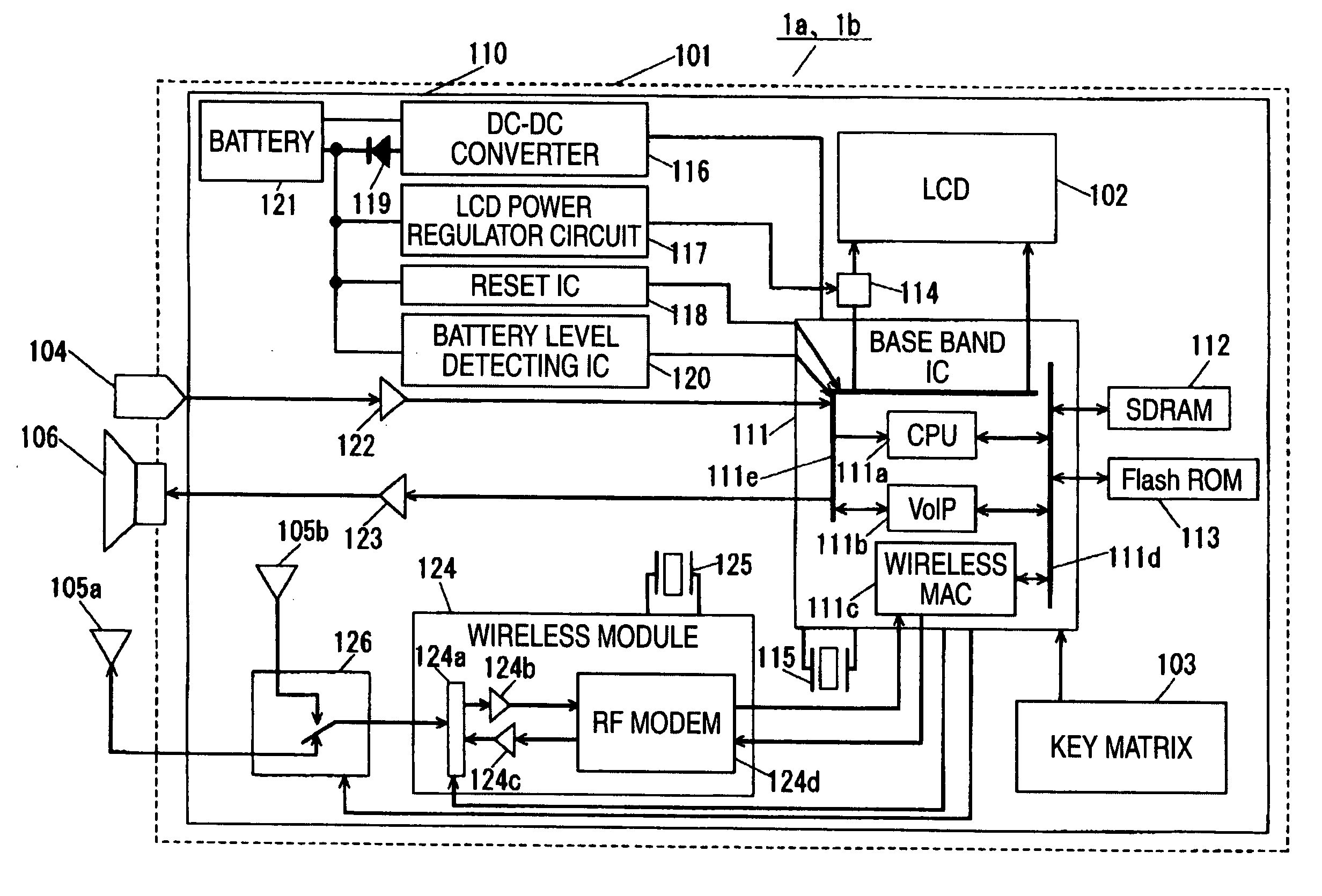
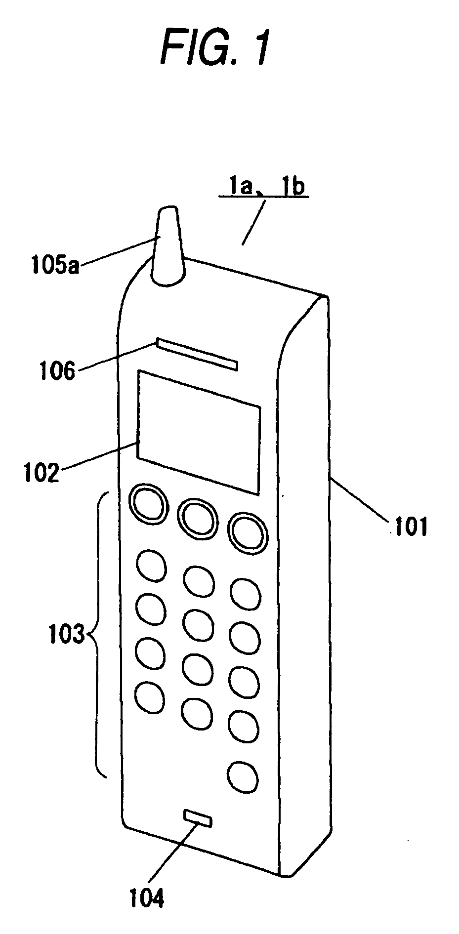
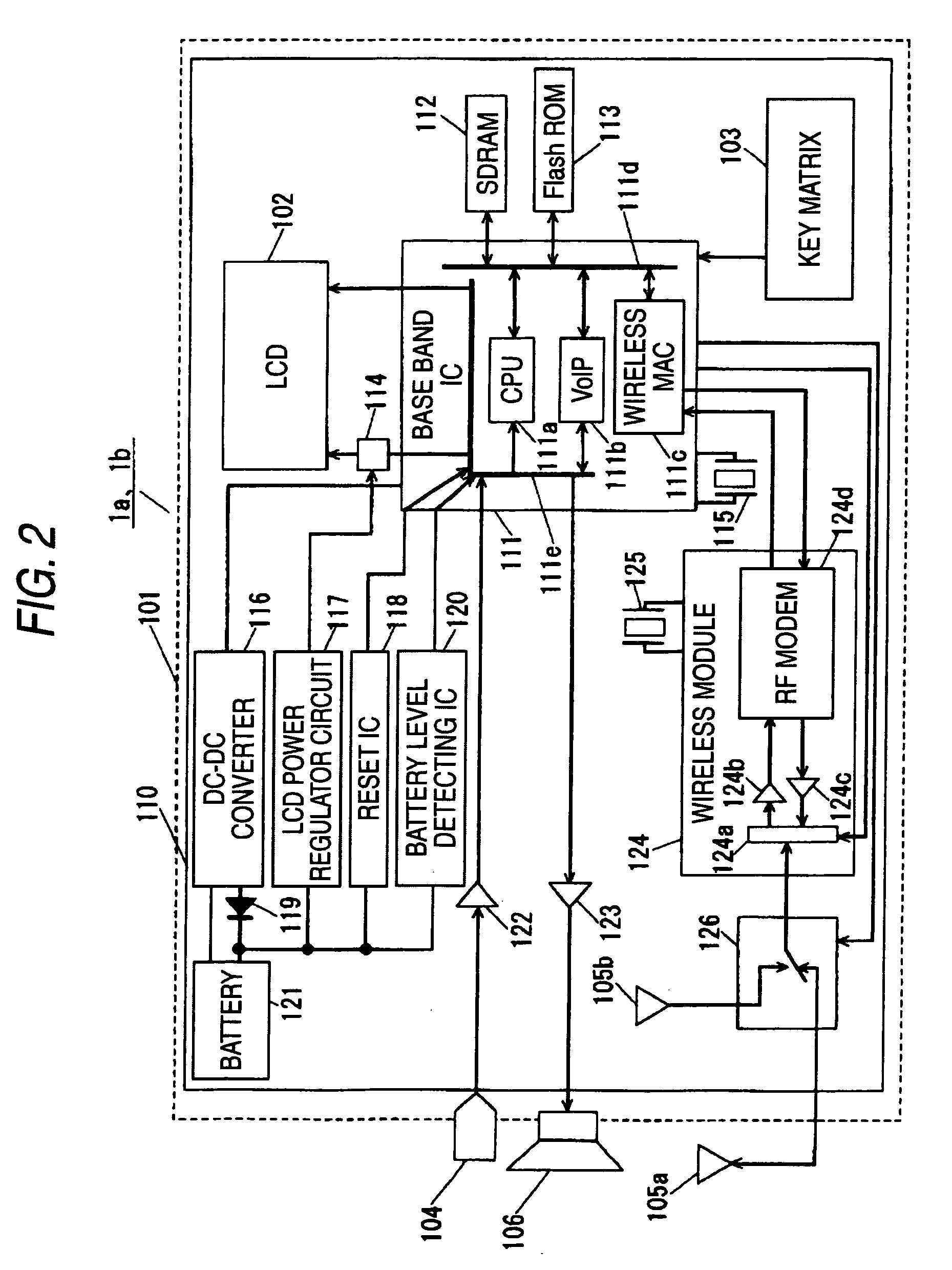
[0030]A first embodiment of the invention will be described with reference to FIGS. 1 to 8. FIG. 1 is a perspective view illustrating the appearance of a communication terminal according to the first embodiment. In FIG. 1, Reference Numerals 1a and 1b denote communication terminals and Reference Numeral 101 denotes a housing of the respective communication terminals 1a and 1b. Reference Numeral 102 denotes an LCD (Liquid Crystal Display) which is formed on the outer surface of the housing 101 and displays a telephone number, etc. Reference Numeral 103 denotes a key matrix which is formed on the outer surface of the housing 101 and is constituted by buttons for designating telephone numbers, etc. Reference Numeral 104 denotes a microphone which is formed on the outer surface of the housing 101. Reference Numeral 105a denotes an antenna which protrudes from the outer surface of the housing 101 and which transmits and receives radio waves. Reference Numeral 106 denotes a speaker which ...

second embodiment

[0089]A second embodiment of the invention will be described with reference to FIGS. 6, 7, 9, and 10. FIGS. 9 and 10 are time charts in a communication system according to the second embodiment. Communication terminals 1a and 1b are each a power saving communication terminal which repeats power-on and power-off operations. A management terminal 2 and the communication terminal 1a are embodied according to the invention, but the communication terminal 1b is not embodied according to the invention.

[0090]That is, at a normal time, a main control section 111a1 of the communication terminal 1a sets a minimum upper limit value and a maximum upper limit value of a random number generation range on a transmission wait time setting section 111c2. At the time of transmitting a frame, the transmission wait time setting section 111c2 sequentially increases a range of selecting wait time before frame transmission from the minimum upper limit value, whenever the frame is retransmitted. However, w...

third embodiment

[0117]A third embodiment of the invention will be described with reference to FIGS. 6, 7, and 11. FIG. 11 is a time chart in a communication system according to the third embodiment. Communication terminals 1a and 1b are each a power saving communication terminal which repeats power-on and power-off operations. The communication terminal 1a is embodied according to the invention, but the communication terminal 1b is not embodied according to the invention. That is, a main control section 111a1 allows a power-on / ff section 111a2 to set power-on under the condition that plural frames are stored in a transmission frame content storing unit 112, and the communication terminal 1a transmits the plural frames at one time, when a battery level detecting unit 120 notifies the main control section 111a1 that the remaining battery level has been low. On the other hand, the communication terminal 1b performs a normal frame transmission.

[0118]Until time T11a, the battery level detecting unit 120...


PUM


Abstract

A communication apparatus includes: a battery; a battery level detecting unit which detects a remaining battery level of the battery; a transmitting unit which transmits data; a wait time setting unit which determines an upper limit value from a minimum upper limit value to a maximum upper limit value for a random number generation range, generates a random number up to the upper limit value, and sets a wait time for transmitting the data on the basis of the random number; and a control unit which sets the minimum and maximum upper limit value for the random number generation range on the wait time setting unit. The control unit sets at least one of the minimum and maximum upper limit value in a different manner from a normal control time in case that the control unit receives data indicating that the remaining battery level is detected to be low.

Description

BACKGROUND[0001]1. Technical Field[0002]The invention relates to a communication apparatus including a management terminal which is an example of the communication apparatus and a communication method which includes plural communication apparatuses, the communication apparatus and method are used in wireless communication such as a wireless LAN.[0003]2. Background Art[0004]Recently, a wireless communication network has been established, and connection of portable wireless communication terminals to the network has generally been made. Since it is difficult to constantly supply the portable wireless communication terminals with power from the wall socket, a battery is used as a driving source. However, when a remaining battery level becomes low, it is also difficult to charge the battery in many cases. Accordingly, suppressing unnecessary power consumption has been carried out in such a way that information on the remaining battery level is notified to set a transmission speed, a tra...

Claims


Application Information

Patent Timeline
IPC IPC(8): H04B1/38H04M1/00H04M1/725H04W24/00H04W52/02H04W74/08
CPCH04M2250/06Y02D70/23Y02D70/142H04W52/0261Y02D30/70
Inventor TANAKA, HIRONORI
Owner PANASONIC INTELLECTUAL PROPERTY MANAGEMENT CO LTD
Why Eureka
Try Eureka