Safety Blood Collection Assembly With Indicator

a technology of safety needles and assembly parts, applied in the field of shieldable safety needle assemblies, can solve the problems of time required to ensure venous, cumbersome shieldable needle assembly availability, and practitioners may be rushing and forgetting to operate the safety shield, so as to reduce the risk of exposure to medical personnel, convenient to use, and cost-effective

Active Publication Date: 2008-12-25
BECTON DICKINSON & CO
View PDF108 Cites 95 Cited by
  • Summary
  • Abstract
  • Description
  • Claims
  • Application Information

AI Technical Summary

Benefits of technology

[0012]A need continues to exist for safety needle assemblies incorporating both a visual flash indicator and a safety shield that can be transitioned from a retracted position in which the tip of a needle cannula is exposed, to an extended position in which the tip of the needle cannula is shielded, which minimizes the risk of exposure to medical personnel, is convenient to use, and is cost-effective.

Problems solved by technology

However, many medical practitioners consider the available shieldable needle assemblies cumbersome.
Additionally, in some cases, practitioners may be rushing and forget to operate the safety shield.
Another problem with many prior art blood collection devices relates to the time required to assure venous entry.
However, there are many instances in which a medical practitioner will properly access a vein with the distal end of the needle cannula, but will mistakenly believe that the vein has not been entered.
This adds to the discomfort for the patient, extends the time required to carry out a blood collection procedure, and increases the risk for accidental contact between the medical practitioner and a cannula that has been exposed to the patient's blood.
Additionally, in some instances a passive shielding mechanism will be activated when the cannula is withdrawn from the patient, thereby making the needle cannula unusable and requiring the medical practitioner to obtain a new needle assembly.

Method used


Image

  • Safety Blood Collection Assembly With Indicator
  • Safety Blood Collection Assembly With Indicator
  • Safety Blood Collection Assembly With Indicator

Examples


Embodiment Construction

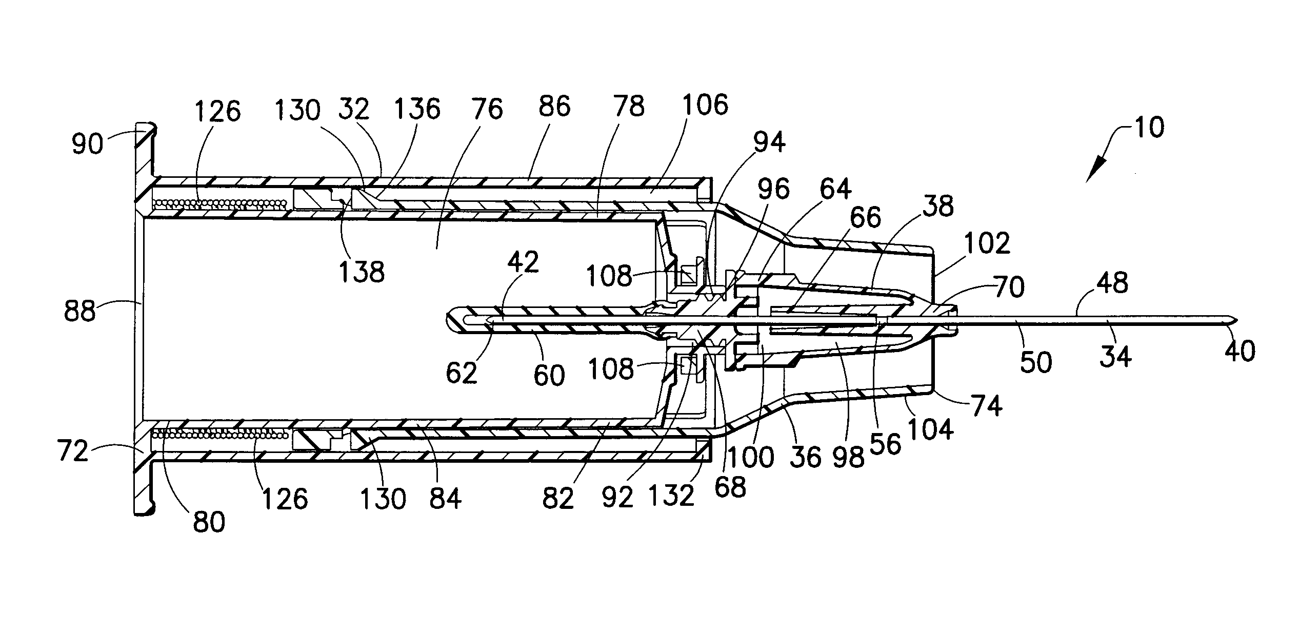
[0167]In general, the needle assembly of the present invention allows for access of a patient's vasculature by a needle cannula, visual indication of vasculature access, and subsequent safety shielding of the needle cannula to protect medical practitioners.

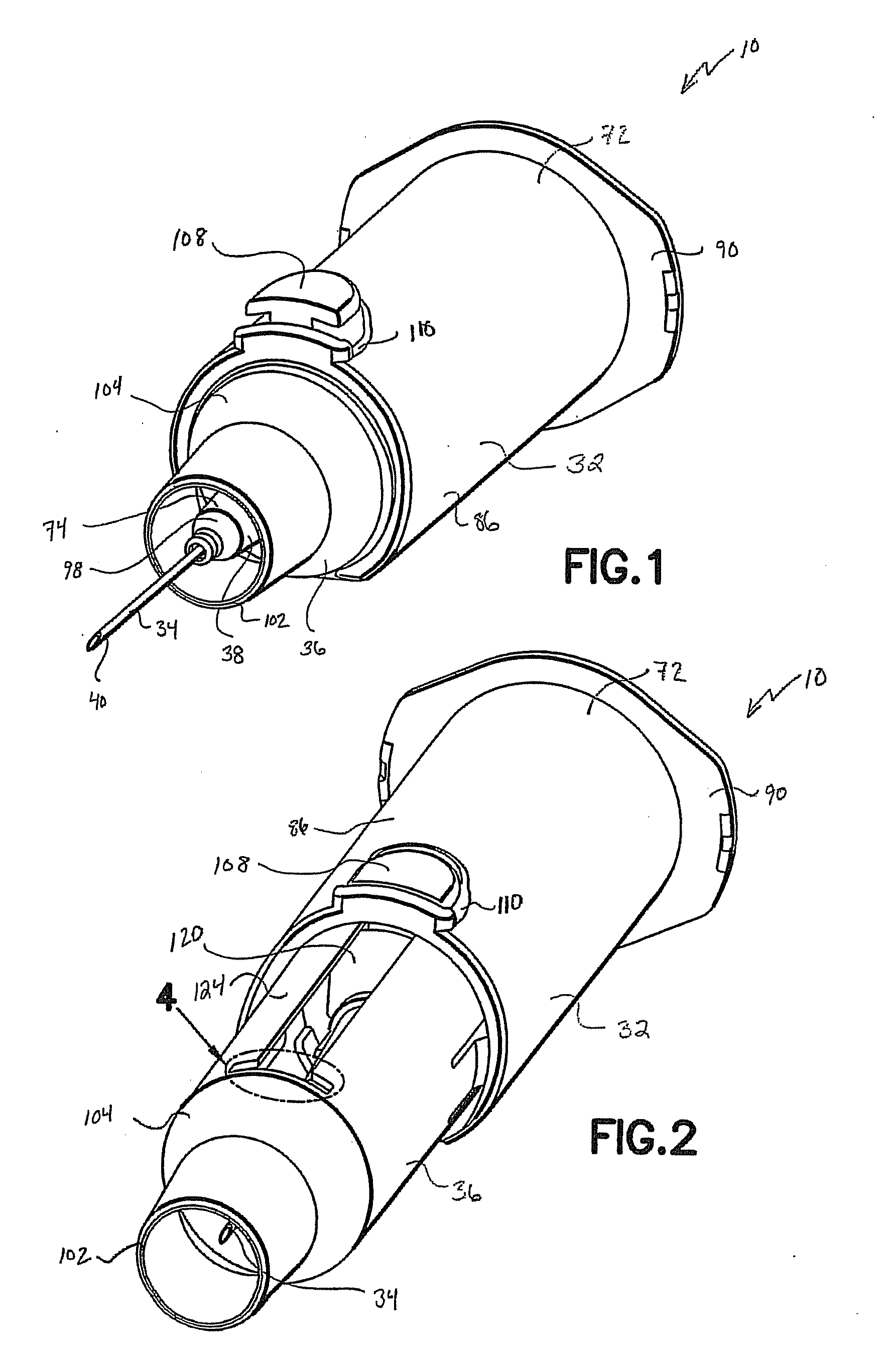
[0168]In one embodiment of the present invention, a needle assembly 30 is provided, as generally shown in FIGS. 1-10. The needle assembly 30 generally includes a housing 32 having a flash chamber 38 integral therewith, a cannula 34 associated with the housing 32, and a safety shield 36 adapted to transition from a retracted position, shown in FIG. 1, to an extended position, shown in FIG. 2, for safety shielding of the cannula 34 during and / or after use of the needle assembly 30. The needle assembly 30 is shown in the retracted position ready for use in a specimen collection procedure, such as a blood collection procedure, in FIG. 1, and after use in the extended position shielding the cannula in FIG. 2.

[0169]With particular refer...


PUM


Abstract

A needle assembly is disclosed. The needle assembly includes a housing having a flash chamber, and having a distal end and a proximal end engageable with a specimen collection container. The assembly includes a cannula having a patient end, a non-patient end, and a sidewall extending therebetween defining a cannula interior. The patient end of the cannula projects at least partially from the distal end of the housing, and the cannula interior is in fluid communication with the flash chamber. The assembly further includes a shield restrainably engaged with a portion of the housing and axially transitionable over the patient cannula from a retracted position in which the patient end is exposed, to an extended position in which the patient end is shielded by at least a portion of the shield, wherein at least a portion of the flash chamber is visible in the retracted position.

Description

CROSS REFERENCE TO RELATED APPLICATIONS[0001]The present application claims priority to U.S. Provisional Application Ser. No. 60 / 941,870 filed Jun. 4, 2007, and U.S. Provisional Application Ser. No. 60 / 893,519 filed Mar. 7, 2007, the entire disclosure of each application is herein incorporated by reference.BACKGROUND OF THE INVENTION[0002]1. Field of the Invention[0003]The present invention relates generally to shieldable safety needle assemblies and, more particularly, to needle assemblies having a housing, a needle cannula, and a shield restrainably engaged with a portion of the housing.[0004]2. Description of Related Art[0005]Typical needle assemblies include a needle cannula having a proximal end, a pointed distal end with a puncture tip, and a lumen extending therebetween. A thermoplastic hub is often mounted securely to the needle cannula at a location spaced apart from the distal end. The hub is typically provided with external threads or other surface configurations for moun...

Claims


Application Information

Patent Timeline
Patent Type & Authority Applications(United States)
IPC IPC(8): A61B5/153
CPCA61B5/1422A61B5/150656A61B5/150633A61B5/153A61B5/15003A61B5/150259A61B5/150389A61B5/150496A61B5/150572A61B5/150595A61B5/150671A61B5/150717A61B5/150732A61B5/1545A61B5/150587A61B5/150603A61B5/1444A61B5/154A61B17/34A61B5/150206A61B5/150564
Inventor CRAWFORD, JAMIESONELLIS, ROBERTWILKINSON, BRADLEY M.BARTFELD, BENJAMINNEWBY, C. MARKTAN, CHEE LEONG ALVINMOH, JONSIM, STANLEYCHIA, NEVILLE YU LENG
Owner BECTON DICKINSON & CO
Why Eureka
Try Eureka