
Flammable substance sensing during a surgical procedure

Active Publication Date: 2008-12-25
SEID ARNOLD STEVEN
View PDF4 Cites 24 Cited by
  • Summary
  • Abstract
  • Description
  • Claims
  • Application Information

AI Technical Summary

Benefits of technology

[0019]This disclosure in one aspect resides broadly in a device, system and method to minimize the likelihood of fires in the operating room and particularly during surgical procedures. A fire usually requires heat / spark (laser or electrocautery), and flammable material (flammable gases, paper or cloth drapes, hair, plastic tubing) and oxygen. Fires are rare in room air but in oxygen and flammable gas enriched environment the risk is greater.
[0020]Electrosurgical cutting divides tissue with electric sparks that focus intense heat at the surgical site. By sparking to tissue, the surgeon produces maximum current concentration. To create this spark the surgeon holds the electrode slightly away from the tissue. This produces greater amount of heat over a short period of time, which results in vaporization of tissue.
[0026]The surgical device can include an element or piece such as a hand piece that is designed for connection to the source of energy and held by the surgeon during a surgical procedure. A surgical tool is supported on the piece or hand piece. The safety apparatus system and method is intended to reduce the possibility of activation of the surgical tool when the oxygen or flammable gas or fluid or substance level is too high.
[0035]The present disclosure aims to provide a safer surgery tool in an environment than has previously been possible.

Problems solved by technology

Fires are rare in room air but in oxygen and flammable gas enriched environment the risk is greater.
This produces greater amount of heat over a short period of time, which results in vaporization of tissue.
A danger is that there may be a high oxygen or flammable gas concentration at the point of the electrocautery device.

Method used


Image

  • Flammable substance sensing during a surgical procedure
  • Flammable substance sensing during a surgical procedure
  • Flammable substance sensing during a surgical procedure

Examples


Embodiment Construction

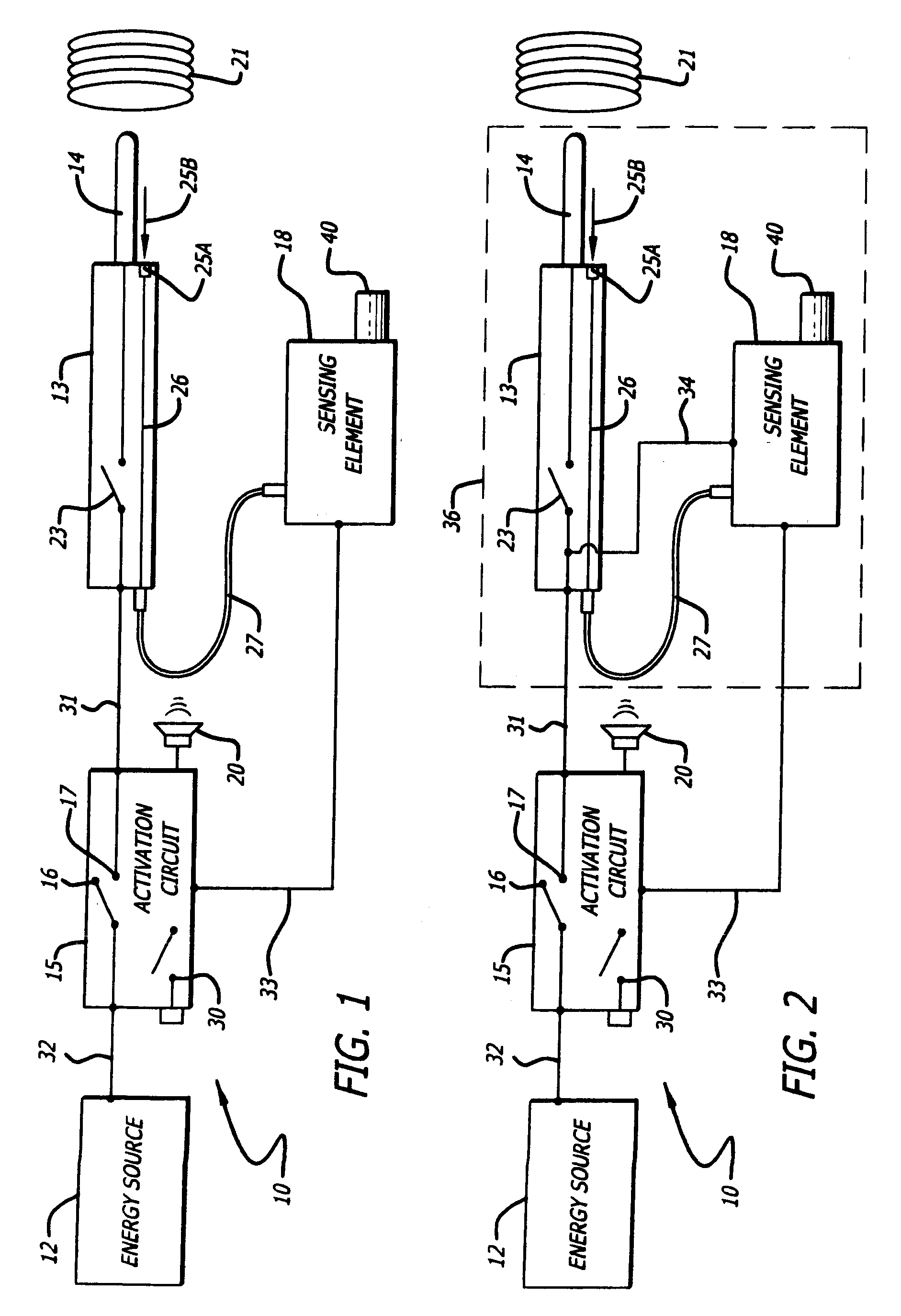
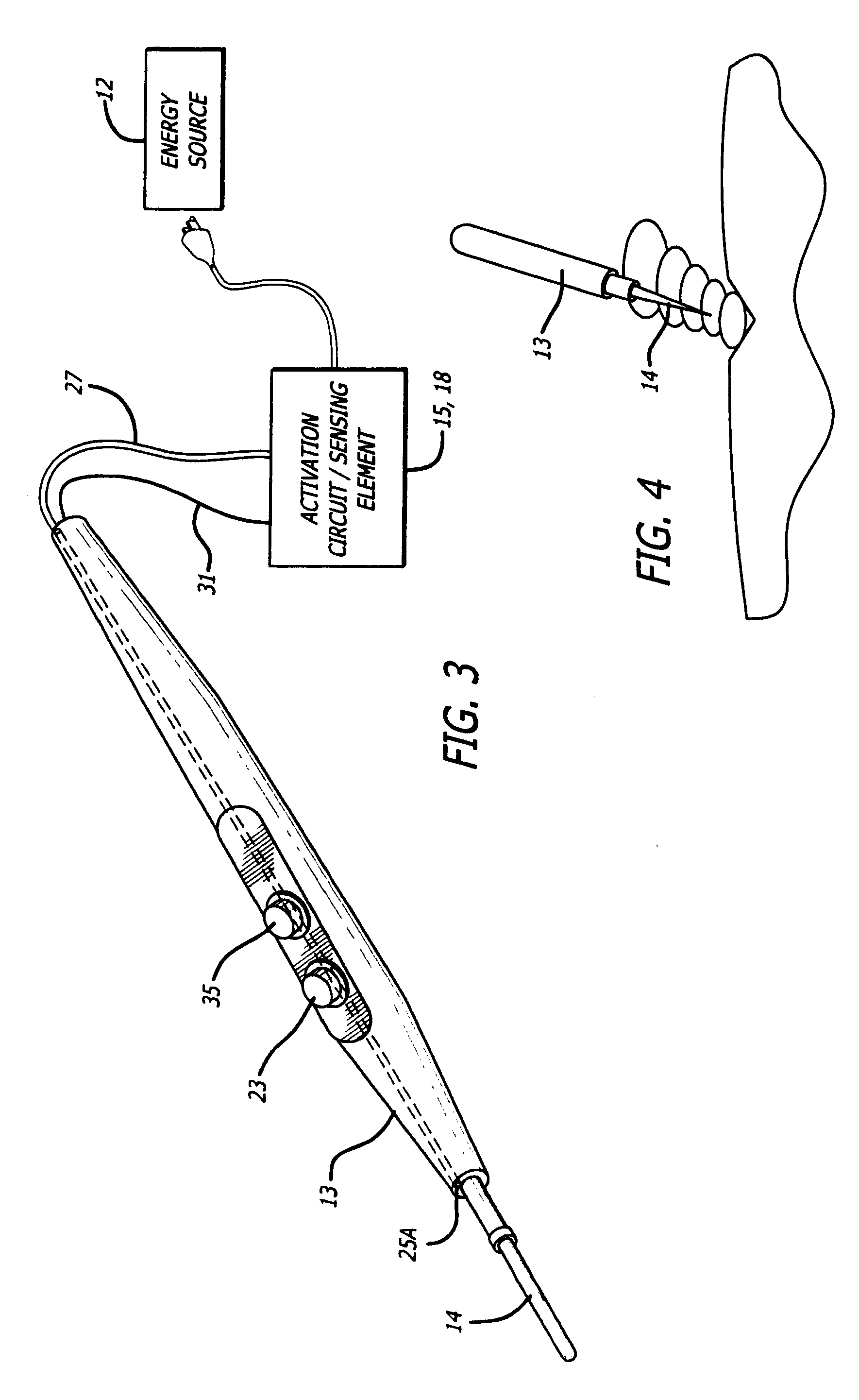
[0042]In FIG. 1 there is a surgical safety apparatus 10 for use in connection with an energizable surgical device. The energizable surgical device includes an energy source 12 and a hand piece 13. The energy source 12 may provide electrosurgical energy, laser energy, and ultrasonic energy. The energy source may provide these energy types individually, concurrently, or in different combinations.

[0043]The hand piece 13 is designed for connection to the energy source 12 and is to be held by the surgeon during a surgical procedure. A surgical tool 14 is supported on the hand piece 13. The safety apparatus is intended to reduce the possibility of activation of the surgical tool when the oxygen or flammable gas level is too high in the environment of the surgical area.

[0044]An activation circuit 15 is connected through line 32 with the energy source 12 and is connected with the hand piece 13. There is a main on / off switch 30 associated with the activation circuit 15. There can also be a r...


PUM


Abstract

A surgical safety apparatus for use in connection with an energizable surgical device minimizes inadvertent activation of a surgical tool when the oxygen or flammable gas level is too high. An activation circuit is connected with an energy source and with a hand piece of the tool. A sensor measures the oxygen or flammable gas near the tool and can operate in a first state to disconnect the energy source from the hand piece. In a second state the source of energy is connected to the hand piece. The sensing element is connected to the activation circuit. The sensing element signals the activation circuit to convert the activation circuit from the first state to the second state provided the oxygen or flammable gas level is safe.

Description

RELATED APPLICATION AND PATENT[0001]This application is a Continuation-in-Part of U.S. patent application Ser. No. 11 / 872,323, filed Oct. 15, 2007, which is a continuation of U.S. Pat. No. 7,291,145, issued Nov. 6, 2007, which claims the benefit of and priority to U.S. Provisional Application Ser. No. 60 / 511,367, filed Oct. 14, 2003, the contents of all of which are incorporated herein by reference in their entirety.BACKGROUND[0002]1. Field of the Disclosure[0003]This disclosure relates to an apparatus and method for measuring the level of flammable gases in relation to the zone of a surgical procedure such as electrocautery. More specifically the disclosure pertains to minimizing inadvertent activation of energizable surgical tools such as an electrosurgical pencil, a laser scalpel, and more particularly a safety switch arrangement.[0004]2. General Background[0005]In general, there is a problem in minimizing surgical fires. In the fire triangle heat, fuel and oxygen are present to ...

Claims


Application Information

Patent Timeline
IPC IPC(8): A61B18/14
CPCA61B18/1233A61B18/1402A61B2017/00119A61B2018/00708
Inventor SEID, ARNOLD STEVEN
Owner SEID ARNOLD STEVEN
Learn More