Heat exchanger fin with ribbed hem

a heat exchanger and fin technology, applied in the direction of tubular elements, lighting and heating apparatus, stationary conduit assemblies, etc., can solve the problems of serpentine fins being subject to compressive forces and the structural integrity of fins is compromised, so as to reduce the structural integrity of fins and increase structural integrity. , the effect of cost-effectiveness

Inactive Publication Date: 2009-01-01
VISTA PRO AUTOMOTIVE
View PDF12 Cites 6 Cited by
  • Summary
  • Abstract
  • Description
  • Claims
  • Application Information

AI Technical Summary

Benefits of technology

[0007]It is another object of the present invention to provide a method for manufacturing split louvered serpentine fins which is cost-effective, yet produces a quality fin.
[0008]A further object of the invention is to provide a method for manufacturing louvered serpentine fins which does not decrease the structural integrity of the fin, and optionally adds increased structural integrity against forces created during the manufacturing process.
[0009]It is yet another object of the present invention to provide a method for manufacturing split louvered serpentine fins which results in fins having consistently high efficiency and heat transfer rates.
[0010]A further object of the invention is to provide a heat exchanger fin which will have exceptional strength against bulging of the core due to internal pressure, against distortion to the fins due to pressure washing, and against damage in service due to road debris.

Problems solved by technology

When louvers are incorporated into the fins, the structural integrity of the fin is compromised.
Additionally, serpentine fins are subject to compressive forces during the heat exchanger manufacturing operation of stacking the fins and tubes to make a core assembly.

Method used


Image

  • Heat exchanger fin with ribbed hem
  • Heat exchanger fin with ribbed hem
  • Heat exchanger fin with ribbed hem

Examples


Embodiment Construction

)

[0039]In describing the preferred embodiment of the present invention, reference will be made herein to FIGS. 1-18 of the drawings in which like numerals refer to like features of the invention.

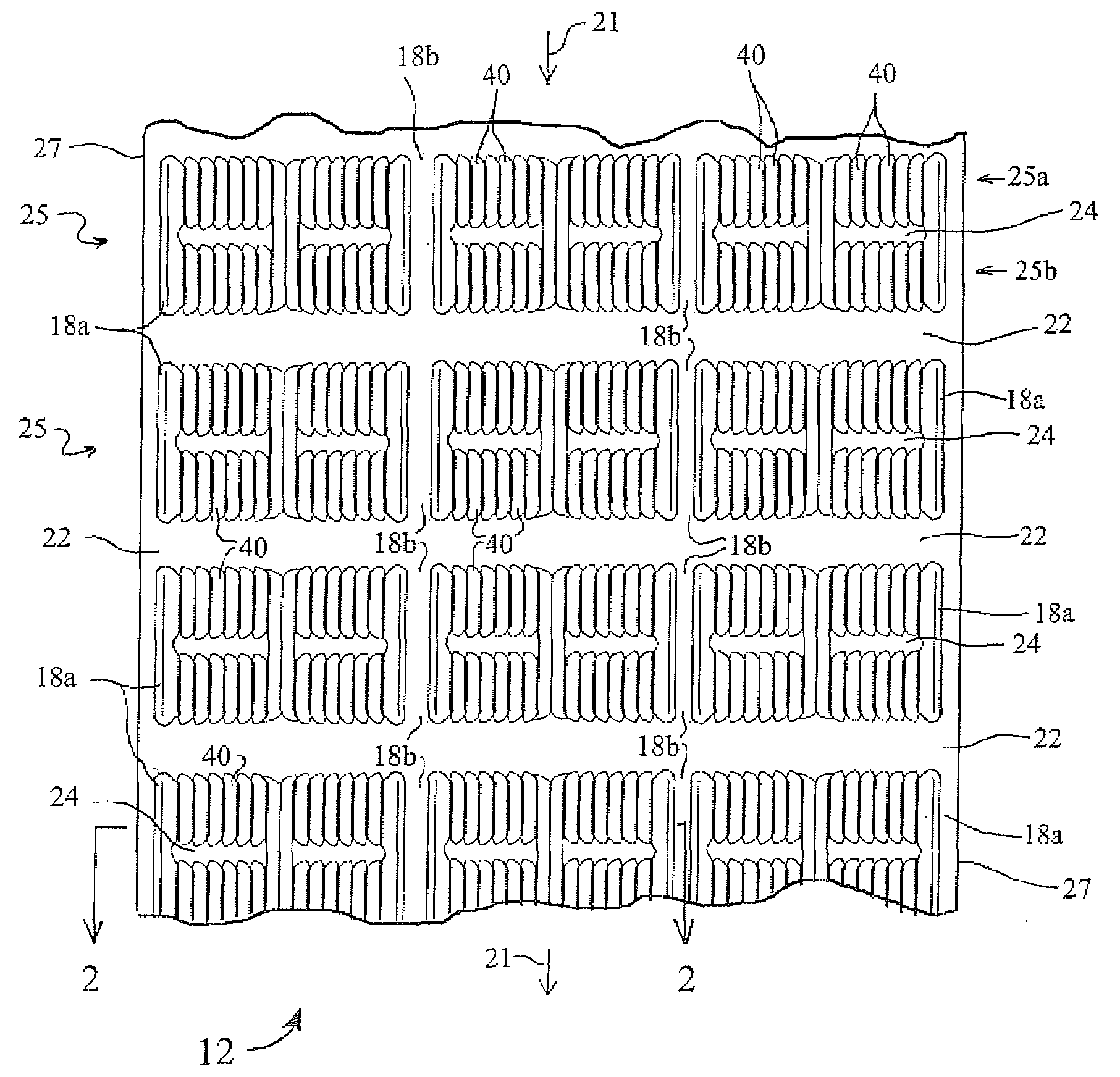
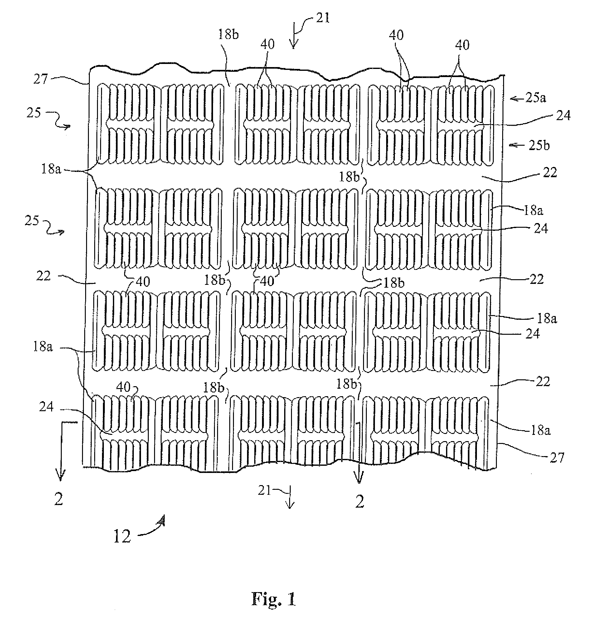
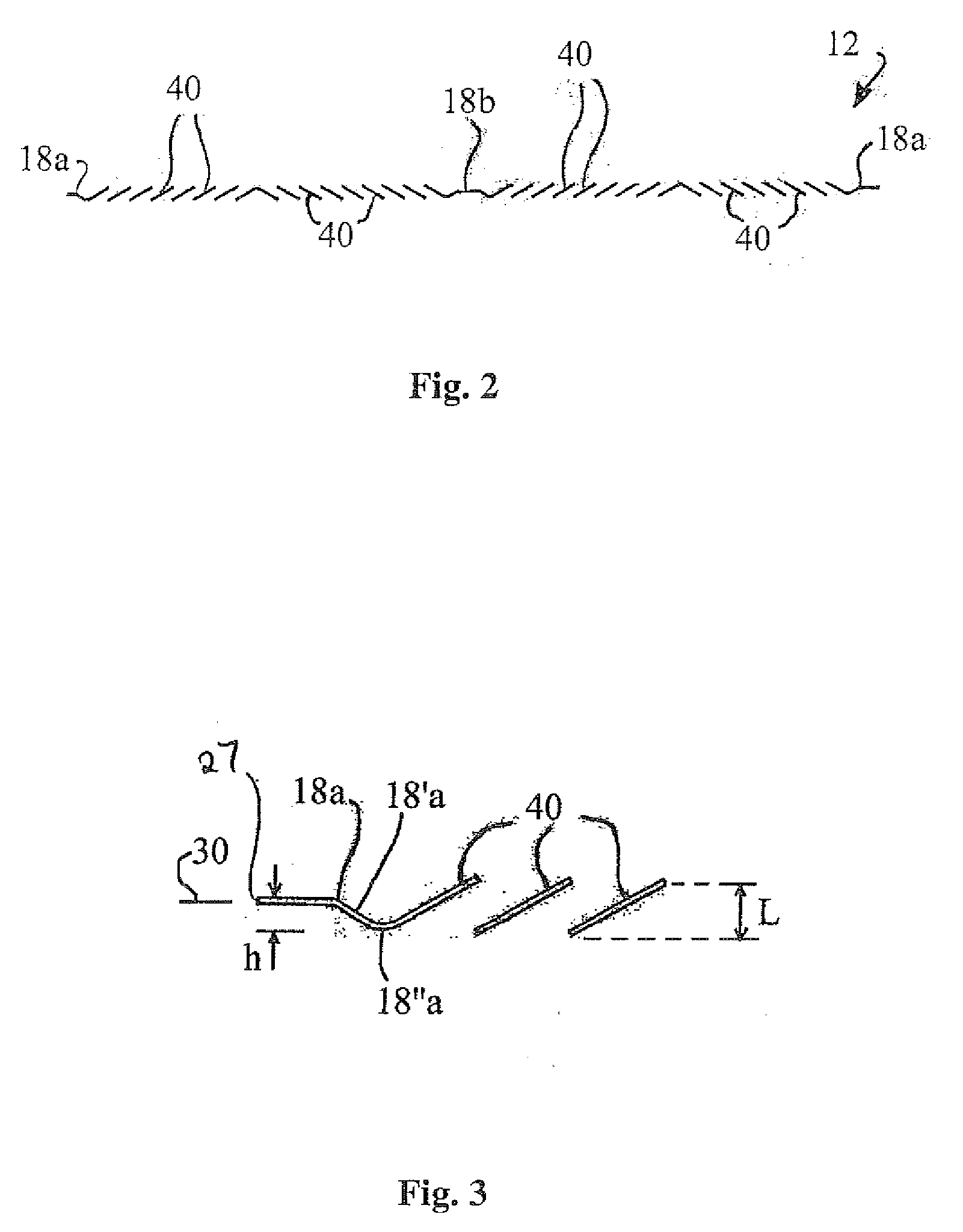
[0040]FIGS. 1-4 depict a split louver fin configuration formed in a flat metal strip in accordance with the present invention, prior to forming the serpentine convolutions. A length of metal strip 12 of aluminum or preferably copper has split louvers 40 extending in rows 25 across the width of the strip, ribs 18a and 18b formed adjacent the louvers within the rows, and unformed portions 22 extending across the strip width between rows of the louvers. The louvers are formed by cutting the strip and twisting and plastically deforming the cut portions. The opposite ends of each of the louvers maintain connection with the remaining metal strip by a twist portion. Each row 25 of split louvers is made up of a pair of banks 25a, 25b of individual louvers 40, which are separated from each other by u...


PUM

PropertyMeasurementUnit
angleaaaaaaaaaa
angleaaaaaaaaaa
thicknessaaaaaaaaaa

Abstract

A serpentine fin for assembly between tubes in a heat exchanger core, and a method of making same from a metal strip. The strip edges have a hem comprising a double thickness of the strip material extending inward from the edge. The metal strip has folds extending across the strip width such that the strip forms a serpentine shape, with the folds being adapted to contact the tubes in the heat exchanger core. Multiple rows of split louvers are disposed between adjacent folds. Each row of split louvers comprises louvers having openings extending in the direction of the strip length and formed in a pair of adjacent, spaced louver banks. Ribs are disposed parallel to the louver openings adjacent the strip edges and in at least one center portion of the strip between the strip edges, and extend across the pair of louver banks.

Description

BACKGROUND OF THE INVENTION[0001]1. Field of the Invention[0002]The present invention relates to the manufacture of heat exchangers and the manufacture of fins for heat exchanger cores primarily used in motor vehicles.[0003]2. Description of Related Art[0004]In the manufacturing of cores for motor vehicle radiators, charge air coolers and other air-cooled heat exchangers, serpentine fins formed from thin gauge metal strip such as copper or aluminum are placed between and in contact with the tubes which carry the fluid to be cooled. The heat exchanger core tubes typically extend between the manifolds, or the inlet and outlet tanks, of the heat exchanger. The fins are the chief heat exchange medium between the coolant and the ambient air. The ability of the fins to transfer heat from the tubes to the air passing over the fins greatly relies on the design of the fins, with some including dimples or protrusions to aid in the heat transfer. To increase the heat transfer rate even further...

Claims


Application Information

Patent Timeline
Patent Type & Authority Applications(United States)
IPC IPC(8): F28D1/03B21D53/02
CPCF28F1/128B23P15/26Y10T29/496B21D35/00B21D53/02Y10T29/4935Y10T29/49378Y10T29/49385F28D1/05383
Inventor KOLB, JOHN A.
Owner VISTA PRO AUTOMOTIVE
Why Eureka
Try Eureka