Card dispensing apparatus

Active Publication Date: 2009-01-01
ASAHI SEIKO CO LTD
View PDF20 Cites 15 Cited by
  • Summary
  • Abstract
  • Description
  • Claims
  • Application Information

AI Technical Summary

Benefits of technology

[0011]To solve this problem, it may be contemplated that a roller made of a soft material is used to increase the amount of deformation of the roller and to increase the contact area between the card and the roller. However, since the abrasion speed of the roller is increased, this can cause a problem.
[0075]Thus, a card can be drawn without upsizing the apparatus even when the amount of stacking cards is increased. Also, since a retracting movement of the conveying member is performed with the first reciprocating member, the second reciprocating member, the guide hole, the interlocked shaft, and the elastic member, the apparatus can be downsized and configured at low cost. In particular, the cards can be pushed higher with the passive hole. Therefore, pushing can be ensured even if the amount of stacking cards is increased.

Problems solved by technology

Therefore, the contact pressure between the roller and the card surface is large.
If the contact pressure of the roller with respect to the card surface is large, when a card made of soft material, for example, when a card made of paper is to be dispensed, the card can be rubbed by the roller and may be damaged.
However, since the abrasion speed of the roller is increased, this can cause a problem.
However, since the apparatus is upsized according to an increase in the diameter of the roller, this can cause other problems.

Method used


Image

  • Card dispensing apparatus
  • Card dispensing apparatus
  • Card dispensing apparatus

Examples


first embodiment

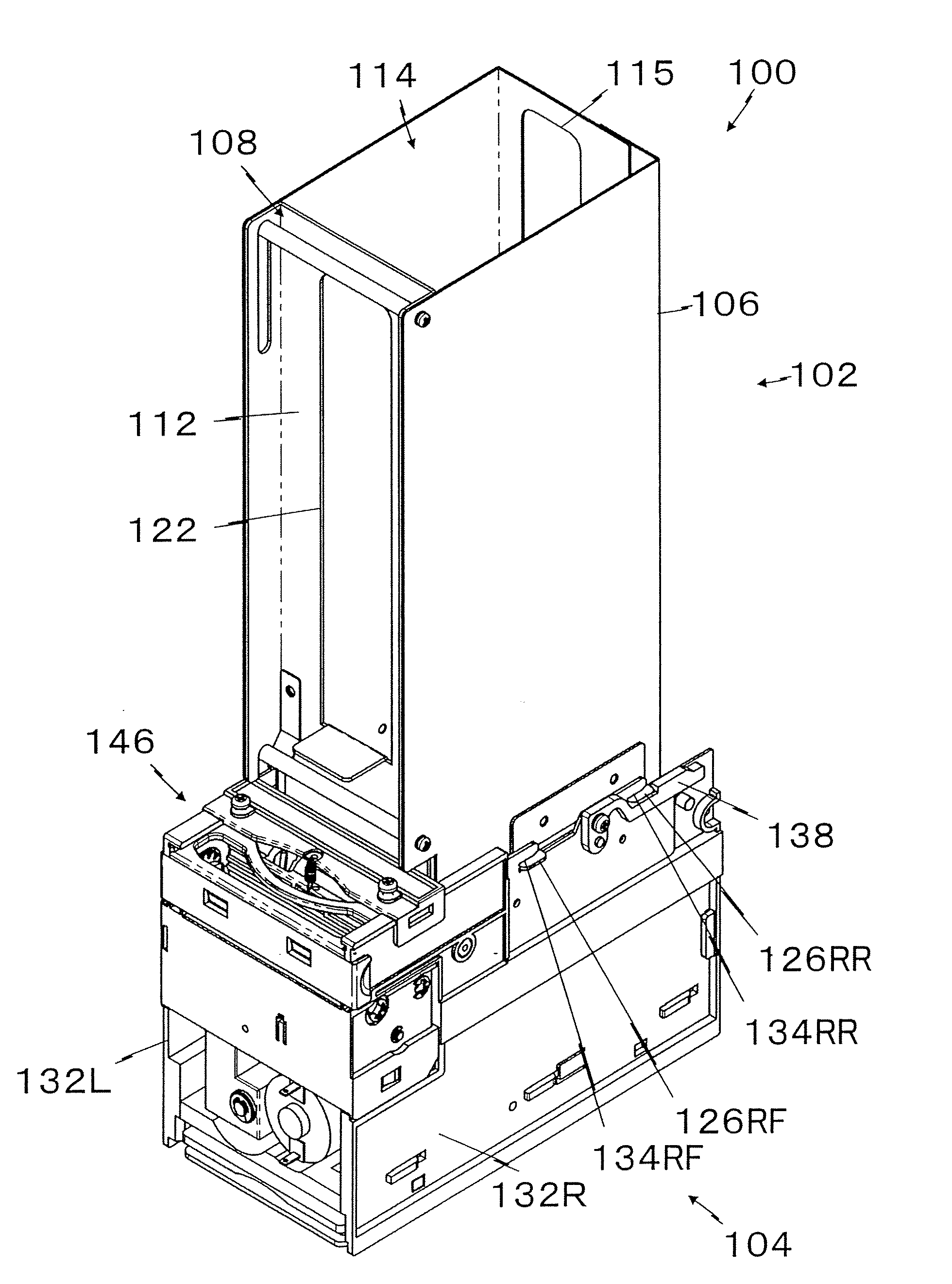
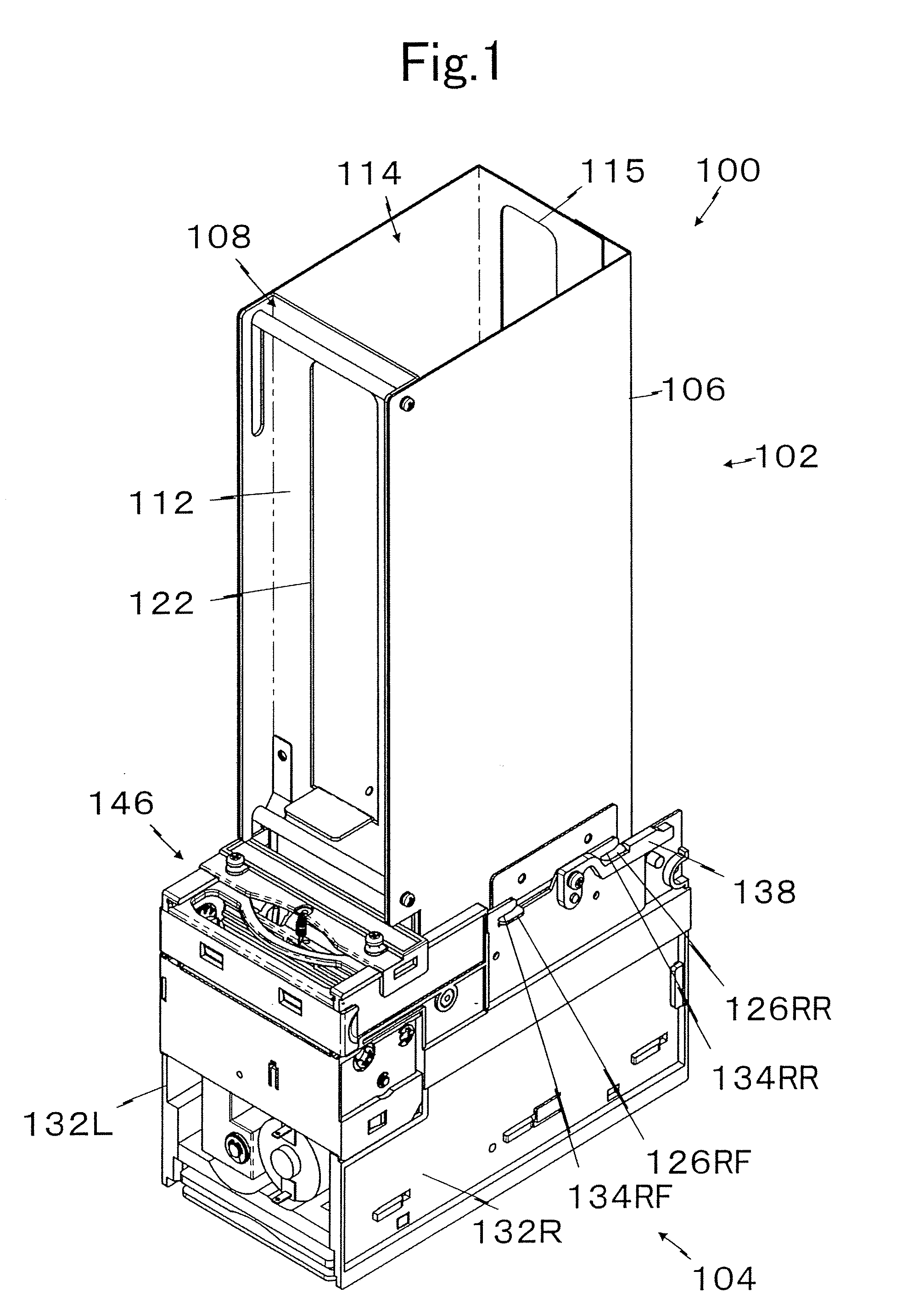
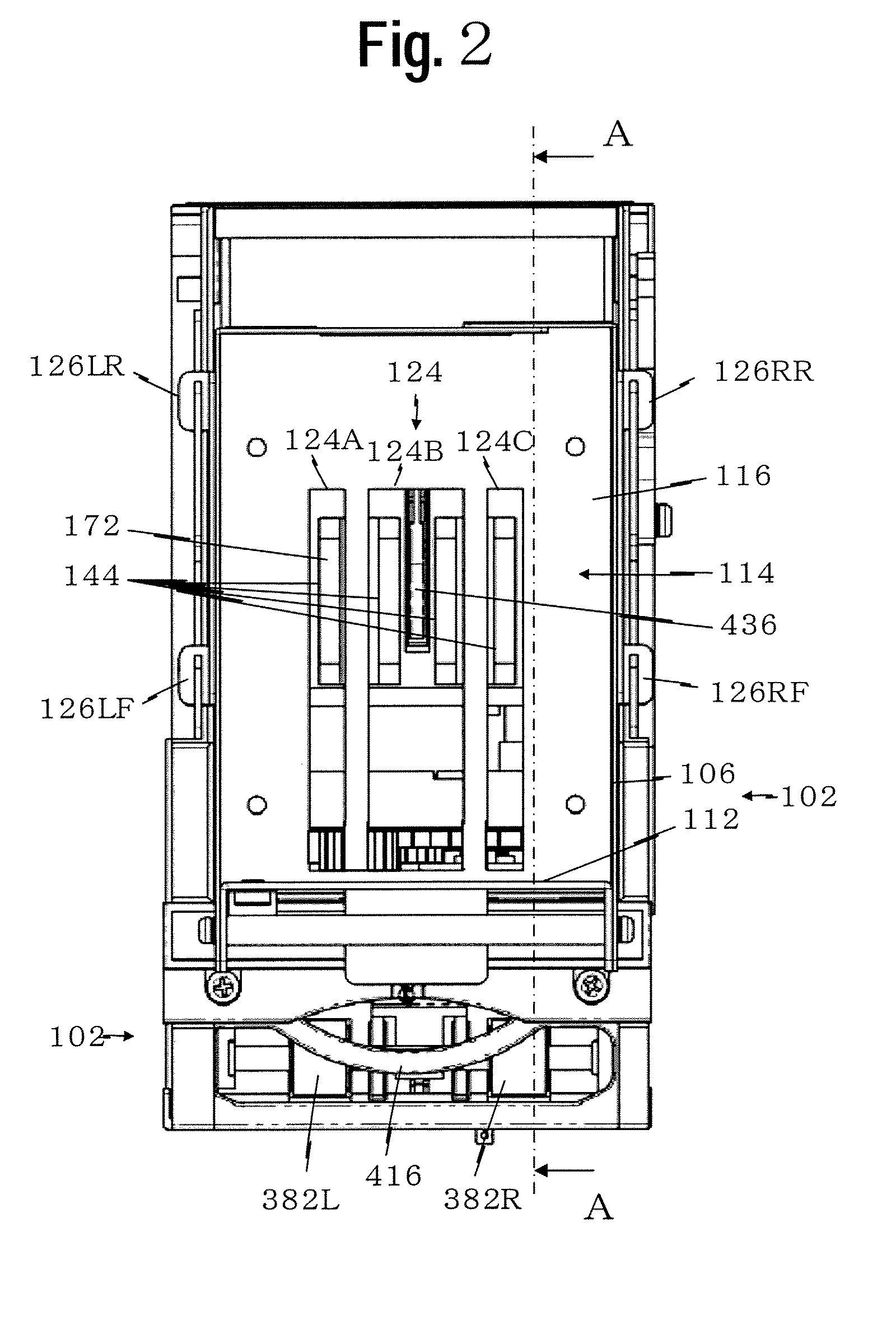
[0234]First, concerns in the card dispensing apparatus in the first embodiment are described with reference to FIG. 23.

[0235]In this card dispensing apparatus, at the time of initial setting, the card C at the bottom is positioned inside the holding room 114 (refer to FIG. 23 (A)). When the card C at the bottom is dispensed to a drawing unit 148 side with a dispensing movement of the dispensing unit 104, the card C at the bottom passes through a gap between the roller 335 and the reverse-rotation roller 336 to advance to a feeding unit 334 side. A card C2 thereon is drawn together with a frictional contact, but is prevented from advancing by the reverse-rotation roller 336 constituting a two-sheet dispensing preventing unit 332, and therefore is not moved to a feeding unit 334 side (refer to FIG. 23 (B)).

[0236]Also, a card C3, which is mounted on the card C2 and which could potentially pass through the exit opening 122, is prevented from advancing by the reverse-rotation roller 336,...

second embodiment

[0240]The second embodiment can prevent such an over-dispensing.

[0241]The second embodiment is described with reference to FIG. 21, where portions identical to those in the first embodiment are provided with the same reference numerals, and only the different portion is described. An inclined surface for pushing 462 is formed at a rear end of the base 116 of the holding member 106 constituting the card holding unit 102. The inclined surface for pushing 462 is inclined downward toward the front at an angle of approximately 45 degrees.

[0242]In other words, the inclined surface for pushing 462 is inclined downward toward the front to the drawing unit 148, and its lower end approaches the exit 122 by approximately five millimeters. With this configuration, several lower ones of the cards C stacked inside the holding room 114 have their rear ends (end portions on a side opposing to the exit 122) make contact with the inclined surface for pushing 462. Then, with the weight of the cards C ...

third embodiment

[0250]the present invention is an embodiment where, since the card is drawn by the feeing unit at a higher speed than the card dispensing unit, even when the amount of stacking cards is increased, difficulty in drawing by the feeding unit can be prevented, as a result, allowing an increase in the amount of stacking cards.

[0251]Specifically, in the card dispensing apparatus according to the first and second embodiments, in the state where the dispensed card is fed by the feeding unit, the conveying member makes contact with the lower surface of the card at the bottom for a predetermined time and the card at the bottom will have approximately the entire weight of the stacked cards applied.

[0252]The conveying member is formed of a material with a high coefficient of friction so as not to cause any sliding with the card as much as possible. With this, when the amount of stacking cards is increased, the contact pressure between the conveying member and the lower surface of the card is in...


PUM


Abstract

A card dispensing apparatus having a compact configuration has a housing to support a stack of cards on a fixed base. Openings in the base member can permit surfaces from a conveying member to extend into the housing and contact a surface of the lowest card. The conveyer member can move horizontal to a release point and retract beneath the base member to return to an initial position. A movement unit provides a cyclic looping movement of the conveyer member into and out of the housing for transporting cards. A feed unit positioned at the dispensing point of the cards can grasp and release the cards from the card dispensing apparatus.

Description

BACKGROUND OF THE INVENTION[0001]1. Field of the Invention[0002]The present invention relates to a small-card dispensing apparatus with increased capacity. In particular, the present invention relates to a card dispensing apparatus that dispenses stacked cards in a predetermined direction without damaging cards from extremely-thin to thick ones irrespectively of card material.[0003]2. Description of Related Art[0004]Here, “card” for use in the present specification is a generic name of a member in a thin plate shape, such as prepaid cards, character cards, IC cards, and others.[0005]As a first conventional technology, a card dispensing apparatus is known in which a perimeter surface of a rotating roller is made to contact with the surface of a bottom card of a plurality of stacked cards and the card is dispensed by frictional contact (for example, refer to Japanese Utility-Model Publication No. 7-26272 (pp. 3-5, FIGS. 1-5)).[0006]As a second conventional technology, a card dispensin...

Claims


Application Information

Patent Timeline
IPC IPC(8): B65G59/06
CPCB65H1/06B65H3/02B65H2403/42G06K13/0843B65H2404/68B65H2701/1914B65H2403/5332
Inventor YAMAMIYA, TAKAHITO
Owner ASAHI SEIKO CO LTD
Why Eureka
Try Eureka